10
Operation Manual
Discharge Fitting
The discharge tting allows the connection of
a high pressure hose. High pressure water ex-
its from this tting. On 15K manifolds, a quick
disconnect is recommended to prevent galling
of pipe threads and damage to the manifold.
Supply Couplings
The supply couplings provide a quick method
for attaching the supply hose to the manifold.
Control Panel
The control panel (Figure 11) is mounted on
the engine next to the clutch. The panel al-
lows the operator to start and stop the engine,
control engine speed, and view engine param-
eters such as coolant temperature and engine
speed.
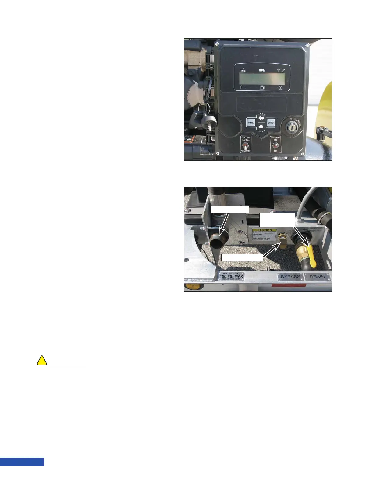
Supply Inlet
The supply inlet tting is located next to the
water pump. The water supply used for water-
blasting is connected at this point.
Bypass Drain
The bypass drain (Figure 12) is connected to
the bypass valve. Water will drain from the
hose onto the ground during pump operation
as explained in “Secondary Filter (40K Units)”
on page 11. This hose can be plumbed to an
alternate drain or tank for collection if re-
quired. If bypass drain water needs to be
routed to a different location, contact Jet-
stream engineering for assistance.
Water Tank Drain Valve
The water tank is equipped with a drain at the
bottom of the tank. The drain tting at the
!!
CAUTION
If a bypass discharge hose is used, the hose
must be properly sized to prevent excessive
backpressure. Excess backpressure can cause
vibration and pulsation in the system leading to
damaged system components.
Figure 11: Control Panel
Supply Inlet
Bypass Drain
Water Tank
Drain Valve
Figure 12: Supply Inlet, Bypass and Water Tank Drains