85
X-Series Waterblast Unit
Installation
1. If shims were under the pump, place the
shims in their proper location.
2. Apply an anti-seize compound to the four
pump mount channels (Figure 175).
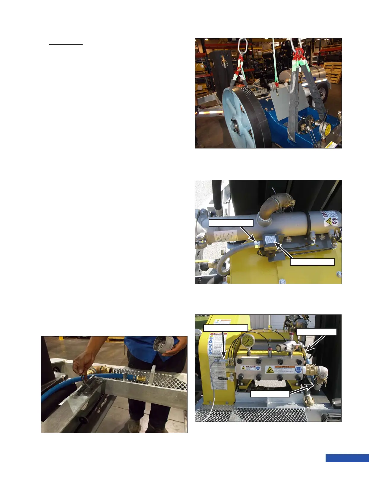
3. Attach a hoist and lifting apparatus to the
pump as shown in (Figure 176). The weight
of the pump is approximately:
• 3000 Series: 1200 lb. (544 kg)
• 3600/4200 Series: 2200 lb. (998 kg)
4. Place the pump into position on the unit
and position the pump near the position
markings that were made during removal.
Once in position, remove the lifting ap-
paratus .
5. Loosely install the pump hardware.
6. Install the belts onto the pulleys. Adjust
the belt tension as outlined in “Adjusting
Belt Tension” on page 73.
7. Install the belt guard.
8. If equipped with a secondary lter, insert
the switch wiring into the switch housing
and connect the conduit tting (Figure
177) to the housing. Connect the wires and
install the switch cover.
9. Place the hydro-throttle switch (Figure
178) in place on the hydro-throttle car-
tridge. Install the two screws that secure
the hydro-throttle switch to the cartridge.
10. Install the bypass hose (Figure 178) and
supply hose.
Figure 175: Apply Anti-Seize to the Pump Channels.
Figure 176: Lifting the Pump.
Conduit Fitting
Switch Cover
Figure 177: 40K Switch Wiring.
Throttle Switch
Bypass Hose
Supply Hose
Figure 178: Connect the Switch and Hoses.