87
X-Series Waterblast Unit
10. Remove the side plate and shims while
supporting the crankshaft. Keep the shims
together.
11. Using a wood block and a hammer, hit
either end of the crankshaft to unseat it
from its bearing bores.
12. Install two threaded rods (1 in.-8NC x 8 in.)
into the ends of the crankshaft to aid in
removal.
13. Using two people, lift the crankshaft from
the power frame. The weight of the crank-
shaft is approximately:
• 3000 Series: 125 lb. (57 kg)
• 3600/4200 Series: 325 lb. (147 kg)
14. Remove the bearings from the crankshaft.
Contact Jetstream for assistance with this
task.
Installation
1. Heat the crankshaft bearings in a 250°F
(121°C) oven for 20 minutes. Check the
bearing color as they are heated. If the
bearings turn blue or black they are over-
heated.
2. When ready, slide the bearings onto each
end of the crankshaft until they are fully
seated (Figure 181).
3. Verify that the bearing turns on the shaft.
4. Allow the crankshaft assembly to cool.
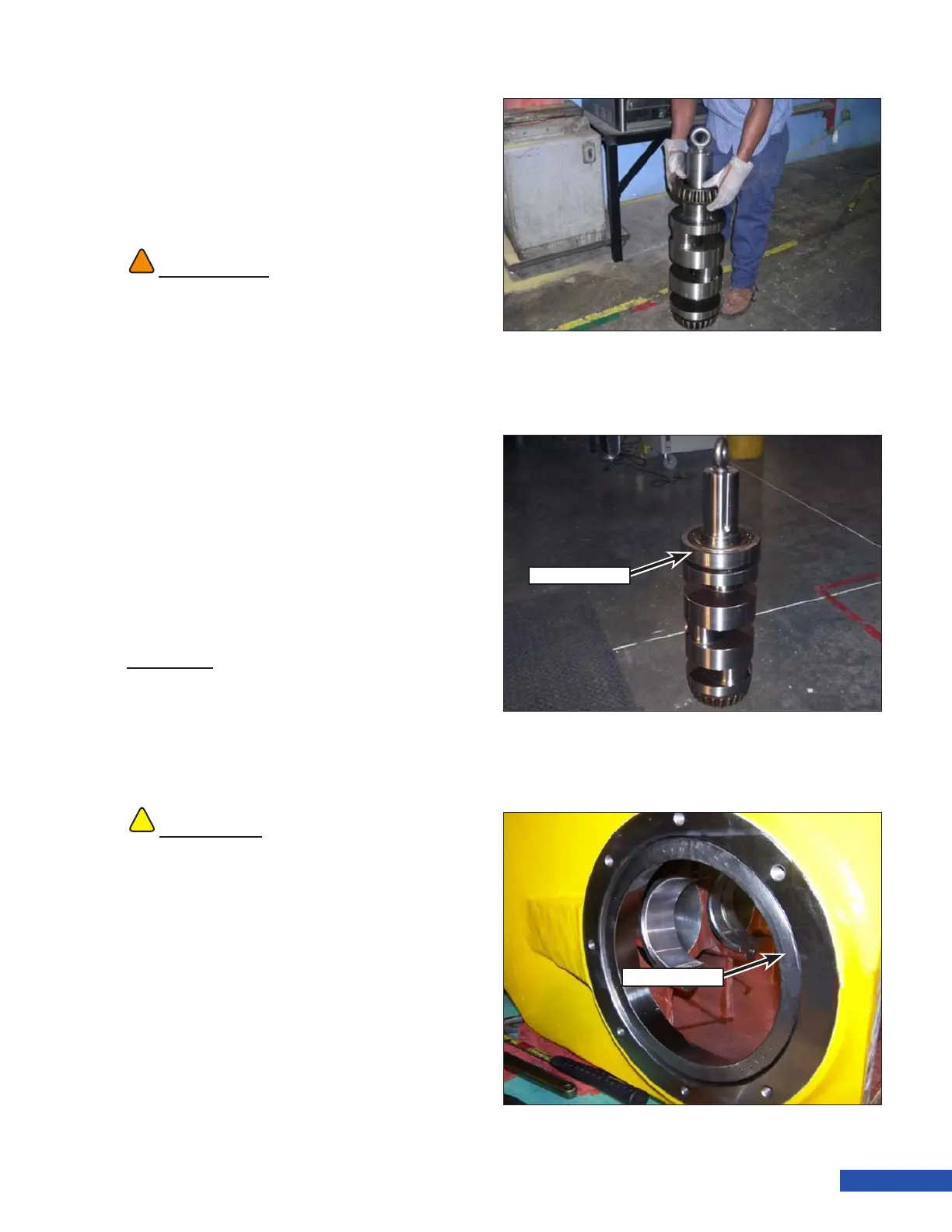
5. Install the outer bearing race (Figure 182)
onto the inboard bearing.
6. Install the outer bearing race (Figure 183)
into the power frame using a rubber mal-
let. Install the race so it is ush with the
face of the case.
WARNING
!!
Use caution when unseating the crankshaft. The
crankshaft will fall approximately 1 in. (25 mm)
as it slides out of the tapered race and can cause
bodily harm.
!!
CAUTION
Temperatures in excess of 250°F (121°C) will
damage the bearing. If the bearings have been
heated over the limit, discard the bearings.
Figure 181: Bearing Installation.
Figure 182: Outer Race Installation.
Outer Race
Figure 183: Bearing Race Installation.
Bearing Race