Unit Specifications and Features
Indoor unit
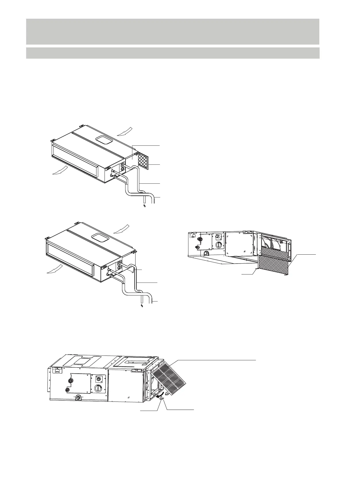
Air outlet
Air inlet
Electric control cabinet
Air filter (on some models)
Drain hose
Refrigerant connecting pipe
NOTE: Different models have different display panel. Not all the indicators
describing below are available for the air conditioner you purchased. Please
check the indoor display panel of the unit you purchased. Illustrations in this
manual are for explanatory purposes. The actual shape of your indoor unit may
be slightly different. The actual shape shall prevail.
(A) For the unit which the filter is removed for left or right side
Refrigerant connecting pipe
Air outlet
Air inlet
Air filter
(on some models)
Drain hose
(B) For the unit which the filter is removed from the bottom side
(C) For the unit which the filter is removed from the back
screw
Air filter
1. Put the filter into the flange subassembly through the bottom side;
2. Lock the screw.
1. Remove two flange coaming;
2. Put the filter into the flange subassembly;
3. Rotate the air filter;
4. Put back to the flange coaming.
screw
Air filter (on some models)
Flange coaming