MODEL
(Btu/h)
Static Pressure
(Pa/in.wg)
0~100/0~0.4
18K
0~160/0~0.64
24K
0~160/0~0.64
30K~36K
0~160/0~0.64
42K~60K
0~50/0~0.2
9K
0~50/0~0.2
12K
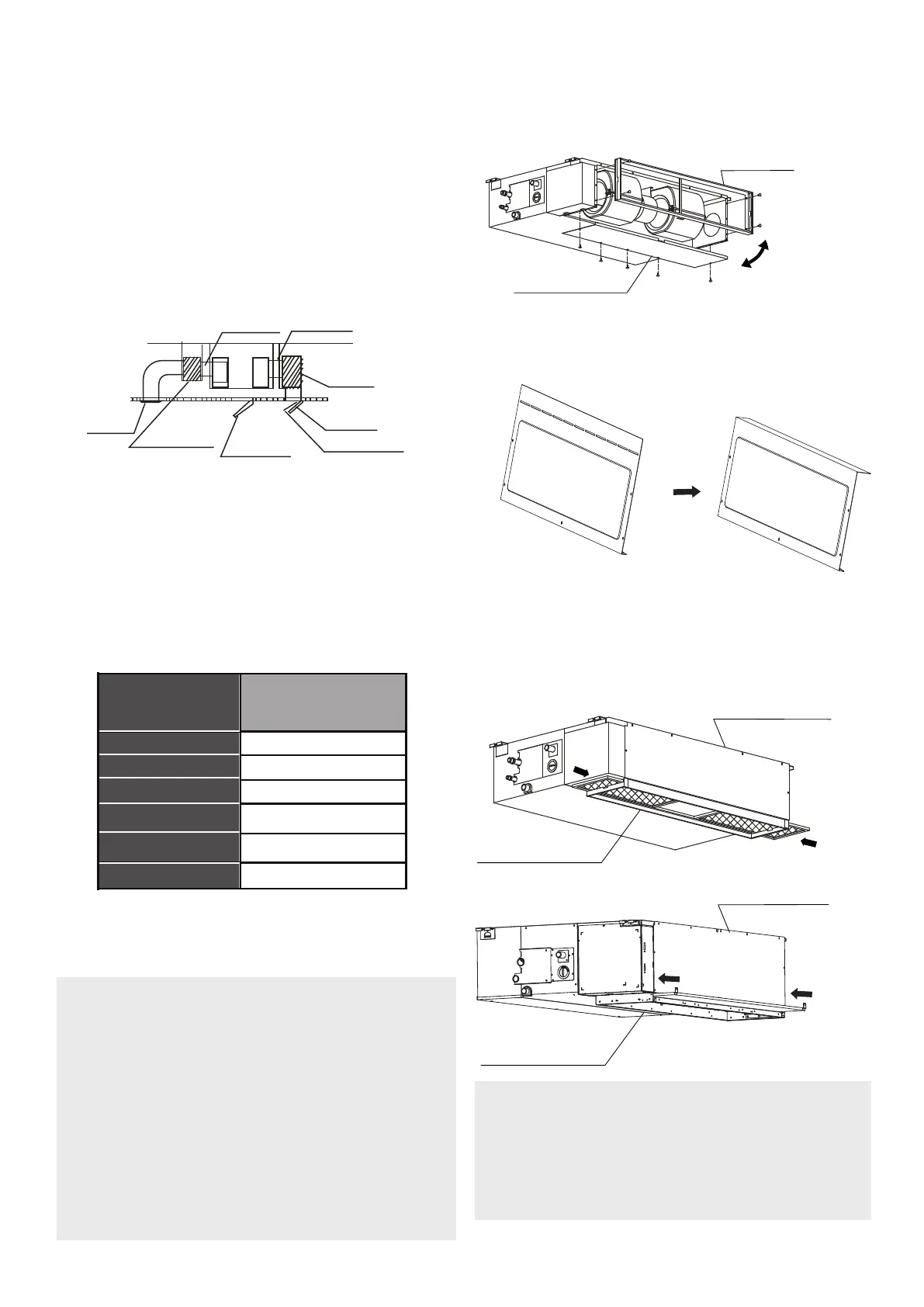
Step 3: Duct and accessories installation
NOTE:
Do not place the connecting duct
weight on the indoor unit. When
connecting the duct, use a non-
flammable canvas tie-in to prevent
vibrating.
Insulation foam must be wrapped
outside the duct to avoid conden-
sation. An internal duct underlayer
can be added to reduce noise, if
the end-user requires.
NOTE:
The min. length of the duct should be
more than 1m, and fix on the air inlet by
screws (applicable to the unit that the
air inlet filter is not fasten by screws).
5. Refer to the following static pressure
guidelines when installing the indoor
unit.
Change the fan motor static pressure
according to external duct static
pressure.
1. Install the filter (optional) according to
the size of the air inlet.
2. Install the canvas tie-in between the
body and duct.
3. The air inlet and air outlet duct should
be far enough apart enough to avoid
air passage short-circuit.
4. Connect the duct according to the
following diagram:
Canvas tie-in Canvas tie-in
Air outlet
Isolation booth
Isolation booth
Checking orifice
Air inlet
Air dust filter
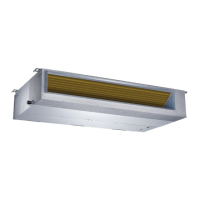
Step 4: Adjust the air inlet direction
(From rear side to under-side)
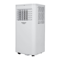
1. Take off the ventilation panel and flange.
Air return flange
Ventilation panel
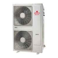
2. Change the mounting positions of the
ventilation panel and air return flange.
3. When installing the filter mesh, fit it
into the flange as illustrated in the follo-
wing figure.
NOTE: All the figures in this manual
are for demonstration purposes
only. The air conditioner you have
purchased may be slightly different
in design, though similar in shape.
Ventilation panel
Air return flange
Ventilation panel
Air return flange
Or
Bend the rear ventilation panel 90 degrees
along the dotted line into a descending
ventil
ation panel. (some models)