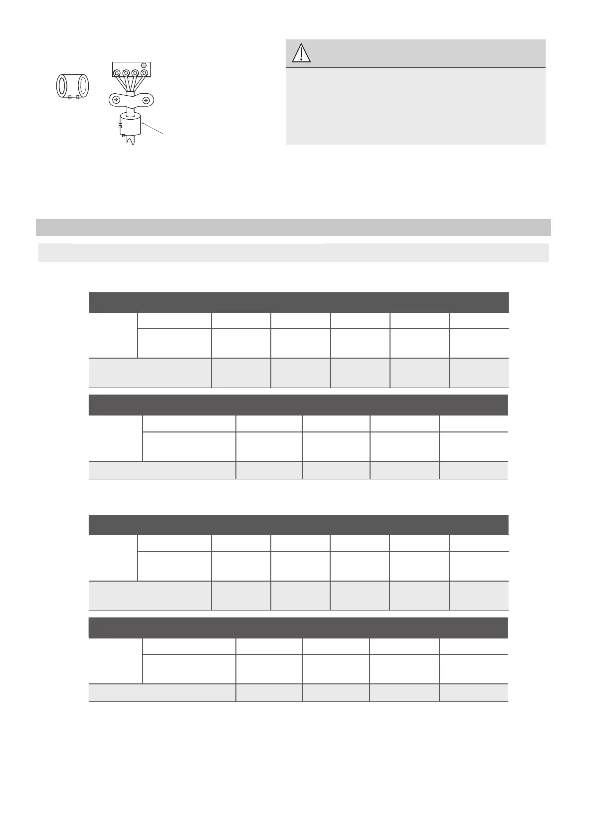
Magnetic ring (if supplied and packed with the
accessories)
1 2 3
Pass the belt through
the hole of the Magne-
tic ring to fix it on the
cable
4. Clamp down the cable with the cable
clamp.The cable must not be loose or
pull on the u-lugs.
5. Reattach the electric box cover.
Power Specifications (Not applicable for North America)
NOTE: Electric auxiliary heating type circuit breaker/fuse need to add more than 10 A.
Indoor Power Supply Specifications
MODEL
(Btu/h)
≤18K
19K~24K 25K~36K 37K~48K
49K~60K
POWER
PHASE
1 Phase 1 Phase 1 Phase 1 Phase 1 Phase
VOLT
VOLT
VOLT
VOLT
208-240V 208-240V 208-240V 208-240V 208-240V
CIRCUIT BREAKER/
FUSE(A)
25/20 32/25 50/40 70/55 70/60
MODEL(Btu/h)
≤36K
37K~60K
≤36K
37K~60K
POWER
PHASE
3 Phase 3 Phase 3 Phase 3 Phase
380-420V 380-420V 208-240V 208-240V
CIRCUIT BREAKER/FUSE(A)
25/20 32/25 32/25 45/35
MODEL(Btu/h)
≤18K
19K~24K 25K~36K 37K~48K 49K~60K
POWER
PHASE 1 Phase 1 Phase 1 Phase 1 Phase 1 Phase
208-240V 208-240V 208-240V 208-240V 208-240V
CIRCUIT BREAKER/
FUSE(A)
25/20 32/25 50/40 70/55 70/60
MODEL(Btu/h)
≤36K
37K~60K
≤36K
37K~60K
POWER
PHASE
3 Phase 3 Phase 3 Phase 3 Phase
380-420V 380-420V 208-240V 208-240V
CIRCUIT BREAKER/FUSE(A) 25/20 32/25 32/25 45/35
Outdoor Power Supply Specifications
CAUTION
While connecting the wires, please
strictly follow the wiring diagram.
The refrigerant circuit can become very
hot. Keep the interconnection cable
away from the copper tube.