8 COMMISSIONING PROCEDURE
FOR THE GENERAL ALARM/PUBLIC ADDRESS SYSTEM COMPACT MPA
8.1 SCOPE
This chapter is valid as commissioning procedure for the General Alarm / Public Address System Compact MPA.
8.2 INTRODUCTION
The purpose of this document is to specify all tesng/measurement to be carried out during the commissioning. The purpose
of the commissioning is to verify that the equipment fulls all funconal requirements. The test objecve is to verify that
cables, terminals and mechanical workmanship of the delivered equipment complies with the specicaons and overall
industry standards for such equipment.
The tests will also show that the basic performance requirements (e.g. Signal Levels and funcons) are met.
These commissioning tests are targeted towards a IMO/SOLAS cered system and relies on the MPA 1600 to congured to
comply with those requirements. Please see the Prerequisites secon of the Operang Procedure for details on the necessary
conguraon opons.
8.3 BRIEF SYSTEM DESCRIPTION
8.3.1 GENERAL
The Public Address & Alarm system is designed, produced and delivered by Jotron. The delivery comprises centralized
equipment mounted in racks, as well as equipment for installaon throughout the vessel.
There are two main purposes for the PA system, one is to broadcast general announcements and the other is to distribute
alarm tones and guide personnel during possible emergency situaons.
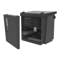
8.3.2 CENTRAL EQUIPMENT
The PA & GA system can be a duplicated system each containing two equally equipped central wall cabinets. Each containing
the MPA 1600 Operaon Unit and the required number of ampliers and distribuon and terminaon modules. Outputs to
eld equipment are divided into separate A and B cable roung.
The system can also be used as a single system with a single cabinet if the redundancy is not required. Field outputs are then
only wired with a single cable roung.
8.3.3 ACCESS & CONTROL PANELS
Up to 24 control units of the types MPA 1601, 1603, 1643 can be connected to the system, divided over 6 user busses. Each
bus can be assigned a priority. Two Control Units (1601 or 1643) and two Alarm Panels (1603) are required to full the IMO/
SOLAS cercaons requirements. A combinaon panel (MPA 1605 or MPA 1606) can fulfull the role of one 1601 and one
1603 in a single device.
8.4 FUNCTIONAL TESTING OF UNITS
8.4.1 MPA 1600 OPERATION UNIT
Below is a descripon of the status lights found on the MPA 1600 central unit and their expected state.
PWR-LED: Green light indicates that power is present on both inputs. Red light indicates the system has not started
yet or the power is missing for one of the inputs.
PA-LED: Green light indicates that there is a PA-message in the system. Otherwise the LED is dark.
AL-LED: Green light indicates that there is an Alarm in the system. Otherwise the LED is dark.
ZONE-LED’s: Green light in a LED indicates that there is acvity in the dened zone.
USER-LED’s: Green light in a LED indicates the acve user in a system. A red light indicates an error in one of the user panels
on the corresponding bus.
Pushing this switch will reset the MPA-system. The switch is protected from unintenonal use, so a pencil-p or
similar must be used to acvate it.
 Loading...