1 485+
Modbus monitoring interface2 485-
3 485_GND
4 Key_in E&M Key
5 Audio/Key_GND E&M Key GND
6 Audio+
E&M audio input
7 Audio-
8 I/O_1
Not in use
9 I/O_2
10 Iso_in_+
11 Iso_in_-
12 Fail relay NO
Amplier failure relay
13 Fail relay C
14 Fail relay NC
15 Power_out_+ Fused 1.5A MPA 24v power output
16 Power_out_GND Fused 1.5A MPA GND power output
9.16 PHONTECH 1671
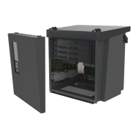
Figure 18: Audio XLR and backup power
As seen in Figure 1. There is a loop for audio consisng of a male and female XLR connector. There is also a
24VDC backup power input.
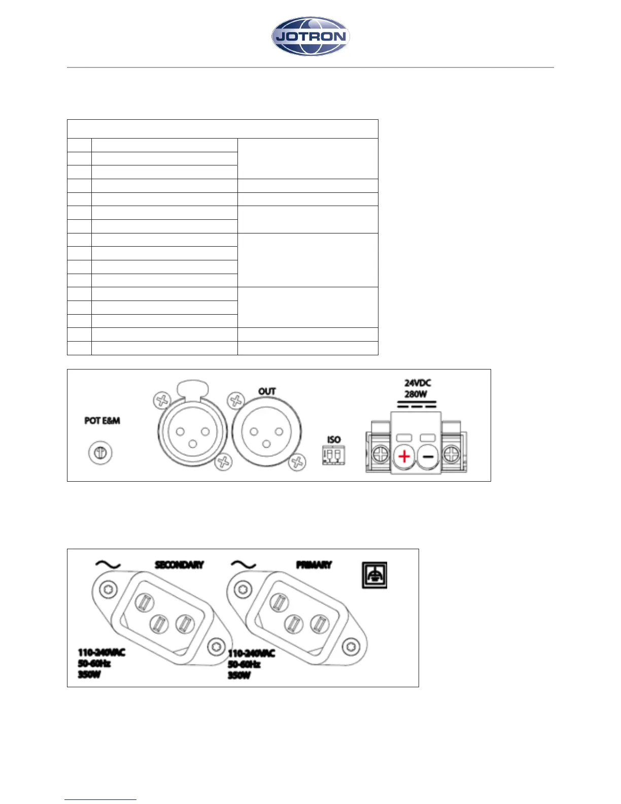
Figure 19: Primary and secondary AC power
As seen in Figure 2. There is a primary and secondary/backup C14 AC power connector.
 Loading...