Chapter 2 INSTALLATION OF THE SCANNER
2.1 SELECTING THE INSTALLATION POSITION
2-4
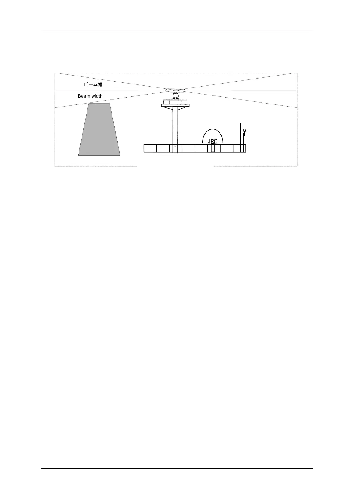
Fig. 2.1-4 Scanner and the surrounding structural objects
Vertical beam width of X-band: Approx. 20° (+/-10.0° when the height of the
radiating section is 0°)
When installing two scanners, provide a height difference so that those two scanners do
not enter each other's vertical beam width range.
To avoid interference with other equipment and to prevent radio noise from generating,
do not place the VHF antenna, GPS antenna, and INMARSAT's dome within the range
of the vertical beam width. Keep a record of installation height data. The data is
necessary for the initial setting of the display unit.
Minimize the blind sector, and ensure the adequate view angle so that the blind
sector does not exist in the range 22.5° from side to rear (Fig. 2.1-5). Specifically,
ensure a sufficient view field in the straight front (relative bearing 000°).
 Loading...

