Chapter 4 ADJUST MENU SETTINGS
4.7 I/F DEVICE
4-32
7 After power-on operation, set the true bearing according to "4.7.1 SET
GYRO".
8 Make sure of the radar video and the operation with the true bearing value.
9 If the true bearing value of the radar equipment is reversed, change the
setting of the switch S5-4.
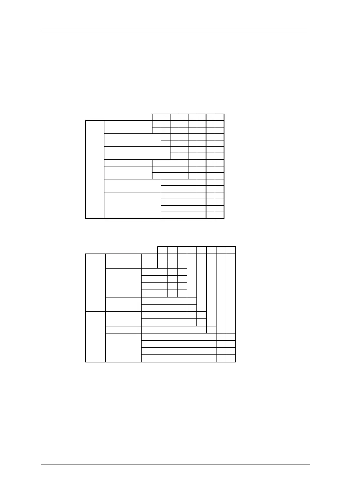
Table 4.7-1 Setting Table (S4 DIP Switch)
12345678
ON
OFF
ON
OFF
ON
OFF
any
ON
OFF
ON
OFF
OFF OFF
ON OFF
OFF ON
ON ON
HEADING SENSOR
SOURCE
NMEA(HDT/THS)
GYRO SIGNAL
4800
9600
19200
38400
OTHER SETTING
LOG ALARM
GYRO SIMULATOR
LOG SIMULATOR
N.C.
Don't care
GYRO ALARM
TIME
NMEA BAUDRATE
SETTING
5s
0.5s
Table 4.7-2 Setting Table (S5 DIP Switch)
12345678
STEP
ON
SYNC
OFF
ON ON
OFF ON
ON OFF
OFF OFF
ON
OFF
ON
OFF
N.C.
any
ON ON
OFF ON
ON OFF
OFF OFF
200P/90×
400P/180×
800P/360×
NOR
RATIO
36×
90×
180×
360×
DIRECTION
REV
GYRO SIGLOG SIG
TYPE
TYPE
SYNC
PULSE
Don't care
PULSE
100P/30×
 Loading...


