1-15
*はA, Bのようにリビジョンを示す。
“*” means revision, such as A, B and so on.
μATX Mother Board
CMC-1323
H-7EUNA4001
CPU:Pentium M 1.6GHz
Main Memory:512MB
CCK-987
Front Panel Circuit 1
CQC-1219
Back Plan M/B
23.1 inch
LCD Module
H-7WSRD0002*
J413
CBD-1831
UPS
Battery
BATT
J
AC IN
BATT
24V IN
NCX-2111
External Interface Unit
W201
H-7ZCNA4061*
W202
H-7ZCNA4062*
W72
E:H-7ZCRD1329A(2m)
ET:H-7ZCRD1330A(5m)
W78
E:KC-V2(2m)
ET:KC-V5(5m)
W208
H-7ZCNA4068*
W209
Ethernet Cable
W302
H-7ZCNA4070*
External I/F Unit
CFQ-5438:W203-W207
/W209/W302/W401/W402/W403
W404
Ethernet Cable
W211
Ethernet Cable
W76
E:VM0301-VM0303B2M
ET:VM0301-VM0303B 5M
NDC-1445/1445T Processing Unit
ACINRGB
BRILL
INLETRGB
BRILL
NWZ-170-E/ET
Display Unit
23.1 inch LCD Monitor
23.1 inch LCD Cable
CML-764-E/ET
W71/W72/W76/W78
W71
H-7ZCRD1328*
W101
H-7ZCNA4027*
W102
H-7ZCNA4028*
W103
H-7ZCNA4029*
W104
H-7ZCNA4030*
W105
H-7ZCNA4031*
W106
H-7ZCNA4032*
W107
H-7ZCNA4033*
W108
H-7ZCNA4034*
Internal Control Unit
CFQ-5437:W101-
W117/W201/W202/W208
CBD-1625
ATX Power
Supply
AC
BATTP
NCM-860 Main Control Unit
W210
DVI Cable
IDE1
TK-412
USB3
USB External Cable
H-7ZCNA4078*
WA-030
CKA-141
ADD CARD
DVI
PS/2
CYC-344
USB Security
Dongle
PCI-X Slot
PCI Slot1
PCI Slot2
AGP Slot
FrontGPO
e-Token
(Option)
Video
GPIO1 GPIO2COM4
ATX
P1
IDE1
IDE2SATA1SATA2
IDE2SATA1SATA2
USB2
USB2
LAN1
LAN2
USB0 USB1 USB3
Video
IDE1
USB3
J201 J202
J206 J213J209J210 J211 J212J208
P201 P202
J207
P207
J203 J204
P7 P12
CDD-719
DVD-RAM
Drive
W113
IDE2P5
CCK-972
LCD Control
Circuit
J7101
P7101
FANALM
D-sub9
PS/2
W114
H-7ZCNA4054*
CCK-986
Front
Panel
Circuit 2
PWR RST
P101
J101
J103
P103
J102
D-sub9
COM3COM2COM1
COM3COM2COM1
NCE-5163-F/FT
Operation Unit
C:W67(2m)
H-7ZCRD1337*
CT:W68(6m)
H-7ZCRD1338*
Internal Operation Unit
CMD-996-E/ET
CCK-976
Operation
Circuit D
CCK-974
Operation
Circuit B
J6401
P6401
J6402 J6403
CCK-973
Operation
Circuit A
J6102 J6101
J6405
J6201
P6102 P6101
P6201
P6402 P6403 P6405
J6406 J6410
P6406 P6410
SPEAKER
W62
H-7ZCRD1332*
W64
H-7ZCRD1334*
W63
H-7ZCRD1333*
W65
H-7ZCRD1335*
J6404
P6404
CCK-975
Operation
Circuit C
J6301
P6301
W66
H-7ZCRD1336*
J6407 J6409 J6411J6408
CMJ-462E
GYRO I/F
(Option)
J1
P4004
CDJ-2373
SRB2
(Option)
J501
P4003
LAN1
LAN2
LAN3
LAN4
J504
CDJ-2373
SRB1
J501
P4002
LAN1
LAN2
LAN3
LAN4
J504
CMJ-519-1
AOB1(Option)
J701
J702
J721
CMJ-519-1
AOB2(Option)
P4001
CBD-1832
Power
Supply
Unit
J402
J813J812
P402
P813P812
TB811
CBD-1832
Power
Supply
Filter
J403 J411 J412
CQD-2128
Radar
Terminal
Board
J651 J653J652
P651 P653P652
W501
H-7ZCRD1510*
W502
H-7ZCRD1511*
W503
H-7ZCRD1512*
TB601 TB602 TB603 TB604 TB605
J404 J407 J408
P404 P407 P408
W401
H-7ZCNA4071*
W402
H-7ZCNA4072*
W403
H-7ZCNA4073*
CQD-2130
Option
Terminal
Board
(Option)
J901 J903J902
P901 P903P902
TB901 TB902 TB903 TB904 TB905
TB
801
TB
802
TB
803
TB
804
P403 P411 P412
CDC-1338
RIB
J601
J610
J620
J611
J621
CDC-1339
RPB
P4005
LAN1
LAN2
LAN3
LAN4
DVI Out
DVI In
RGB
DVI
J604
J603
J605
DVI
J604
J611
J621
CDC-1186D
ARPA PROCESS
W111
Serial ATA1
IDE2 W109
W112
H-7ZCNA4035*
W110
Serial ATA2
CDD-722
USB FD
Drive
USB2
CDD-717
HDD2
SATA2
P3
CDD-717
HDD1
SATA1
P2
CDD-723
F-Disk
P4
W116
CQD-2121
Standard
Terminal
Board
P301 P302P304 P305 P306 P307
J301 J302J303 J304 J305 J306 J307
J308
P4311/2
TB301 TB302 TB303 TB304 TB305
J401 J405J406J409J410
P401 P405P406P409P410
W203
H-7ZCNA4063*
W204
H-7ZCNA4064*
W205
H-7ZCNA4065*
W206
H-7ZCNA4066*
W207
H-7ZCNA4067*
P303
(Option)
Internal Operation Unit
CMD-996-F/FT
RGB
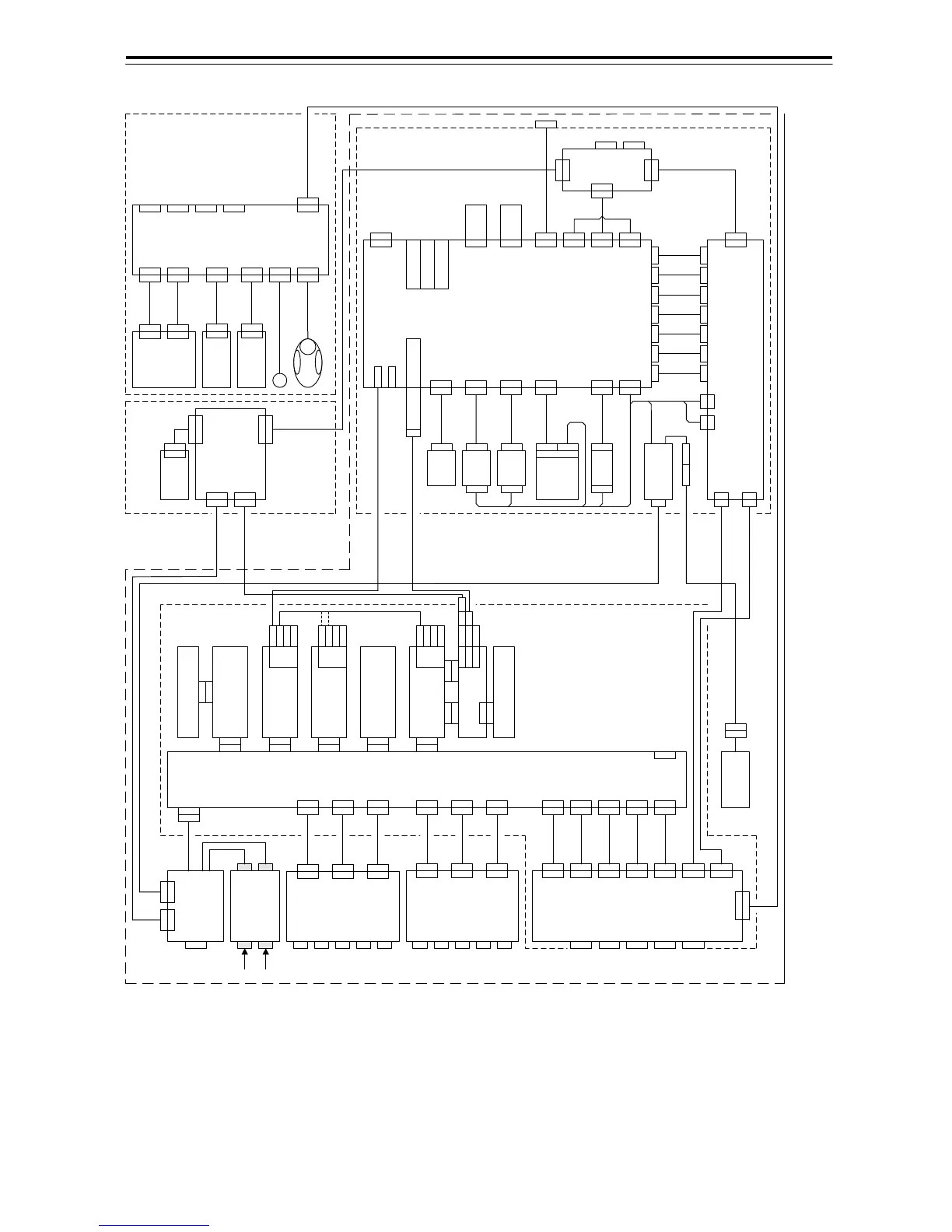
Fig 1-7 NCD-2096 System Configratin Diagram