2-35
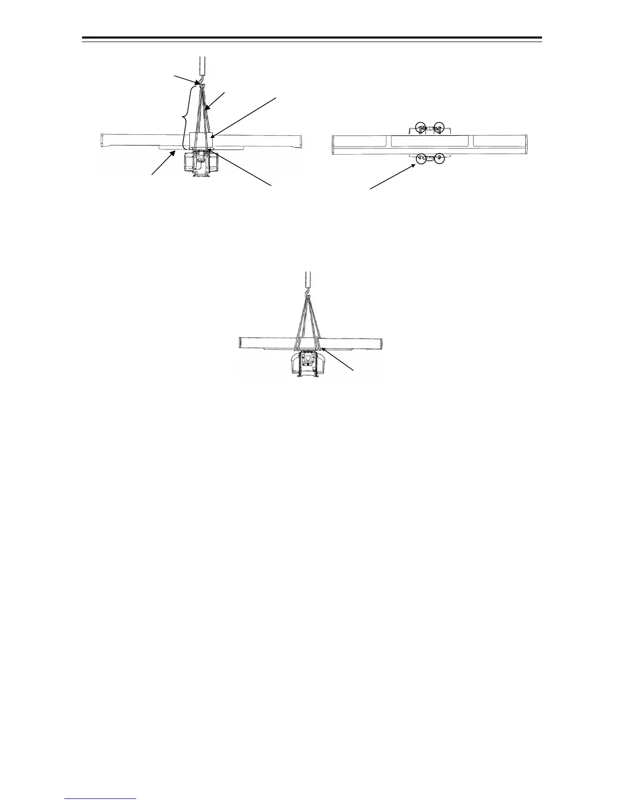
Fig 2-6 S-Band
Fig 2-7 X-Band
2) Insatllation procedures
a) Maintain a flat level surface on which to install the scanner
• Use sufficiently thick steel material and reinforcement material for the
scanner's installation surface (mount base) to reduce vibration and impact.
Keep the mount base flat and smooth.
• If there is a partial gap between the mount base and the scanner chassis's
legs, work on the installation surface so that it becomes flat and smooth, or
make adjustments by inserting metal shims. If a gap exists and the
scanner is tightly clamped, the chassis will distort and become damaged by
vibration.
b) Avoid using vibration-proofrubbe and resin
• Do not insert an elastic body, such as vibration-proof rubber or resin,
between the mount base and the scanner chassis' legs. If rubber or resin
is inserted, the amplitude of vibration increases, resulting in the possibility of
damage to the scanner. Furthermore, if installation bolts become loose
due to deterioration of rubber or resin, the scanner may be damaged or fall
from its mount.
The cloth etc. is rolled.
Top View Side View
Attach a rope to four
hoistin
ebolts
Protector should be located between the rope and the radiator
(Protector is attached on the radiator before delivery)
Over 2.5m
Hook
Rope
Scanner's support section
(Do not use here for hoisting)
 Loading...


