2-36
3) Installation and clamping method
a) Installation direction
• Installation should be done so that the cable gland is oriented toward the
stern.
b) Bolts, unts and tightening torque to be used
• Use stainless steel bolts for the scanner and uniformly tighten all of the bolts
using double nuts for each bolt so that the scanner will not become loose
(Table 2-3).
• Although the length of the bolt will differ according to the thickness of the
mount base, use a bolt long enough so that more than 4 millimeters of
thread protrudes beyond the double nuts after the double nuts have been
tightened.
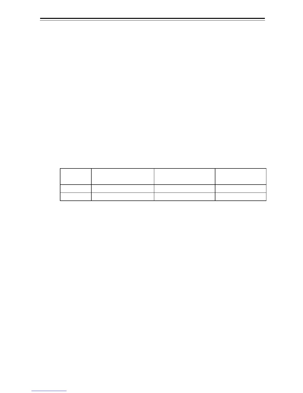
Table 2-3 Length of scanner mounting bolts and tightening torque
Thickness of Mount
Base(mm)
Bolt
Torque
(N-m)
S-band 19 M12×65(mm) SUS304 65
X-band 12 M10×55(mm) SUS304 40