4-10
7) Connect the gyro signal and log signal cables to the terminal block.
8) Set S5 to “ ON ”.
The gyro compass and GYRO I/F are connected.
9) After power-on operation, make sure of the radar video and the operation with
the true bearing value.
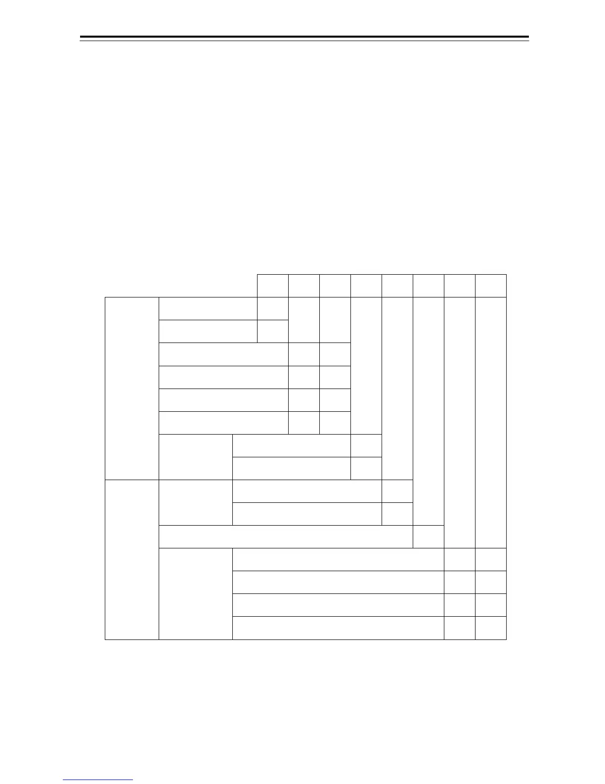
Set default value of GYRO setting. For the setting, refer to Table 4-1
.
10) If the true bearing value of the radar equipment is reversed, change the
setting of the switch S1-4.
S1 設定表/S1 SETTING TABLE
1 2 3 4 5 6 7 8
STEP ON
SYNC OFF
36X ON ON
90X OFF ON
180X ON OFF
360X OFF OFF
逆/REV
ON
ジャイロ信号
GYRO SIG
回転方向
DIRECTION
正/NOR
OFF
パルス/PULSE
OFF
タイプ
TYPE
シンクロ/SYNC
ON
N.C. N.C.
100P/30X
ON ON
200P/90X
OFF ON
400P/180X
ON OFF
ログ信号
LOG SIG
パルス数/NM
PULSE/NM
800P/360X
OFF OFF
Table 4-1 GYRO/LOG SIG switch(S1 DIP)