C-1 Appendix C Setting the Inter switch
Appendix C
Setting the Inter switch
C.1 Overview
C.1.1 Overview
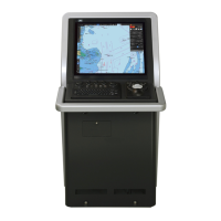
The Inter switch NQE-3141 is equipment that makes it possible to freely select several radar display
units provided in the bridge and the several radar antennas with different properties.
Even when the power supply of the display unit has been switched OFF or has become faulty, it is
possible to operate the radar antennas from other display units.
When it has become impossible to use the Inter switch, it is possible to carry out operations
independently.
The selection can be made up to a maximum of 8 units.
When the radar antenna is switched, the following settings are read out.
Setting Reference
Rough adjustment tuning 14.2.1 Performing basic adjustments on the radar
Bearing adjustment
Range adjustment
Antenna height
14.2.2 Adjusting Radar Antenna
TXRX settings
Performance monitor
adjustment
14.2.3 Adjusting a radar performance monitor
Sector blank 14.2.4 Setting Sector Blank
Radar antenna position 14.3.1 Verifying/Setting CCRP (Consistent Common Reference
The setting of each of coarse adjustment tuning, tuning peak setting, tuning indication level, bearing
adjustment, monitor transmission level (performance monitor adjustment), Tune Indicator (TXRX
adjustment), and Sector Blank is read from the antenna at switching.
Other settings are read from the indicator that is used.
The settings that are saved in the indicator are saved by antenna and the previous setting is read at
the connection.
 Loading...