B
/
21D
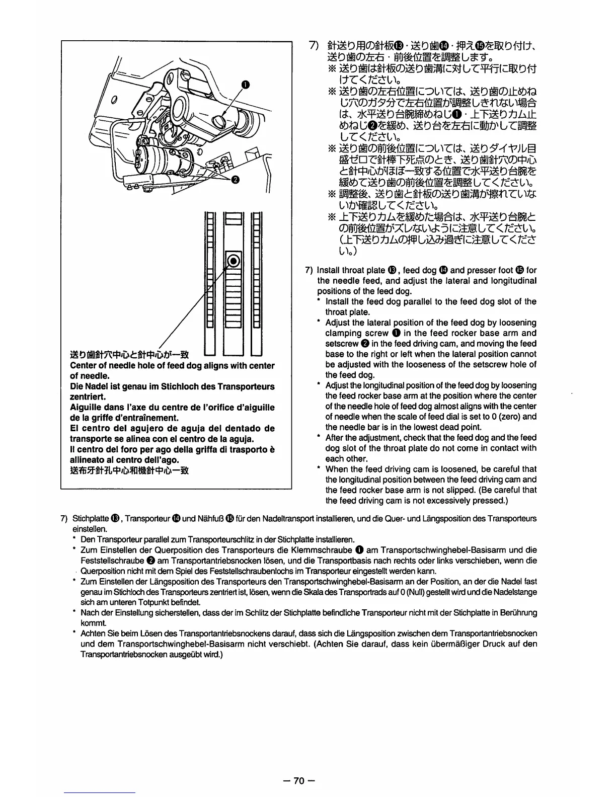
Center
of
needle
hole
of
feed
dog
aligns
with
center
of
needle.
Die Nadel 1st
genau
im
Stichloch
des
Transporteurs
zentriert.
Aiguille
dans
I'axe
du
centre
de
Torifice
d'aiguille
de
la griffe
d'entramement.
El
centro
del
agujero
de
aguja
del
dentado
de
transporte
se
allnea
con
el
centro
de
la
aguja.
II
centro
del
foro
per
ago
della
griffa dl
trasporto
b
alllneato
al
centro
dell'ago.
7)
^
2iDii0:£^iiiKcou^r(^.
mom(D±^u
-70
it.
7j<¥2ID^MI§i^)^UO-±TiSD^A±
ur<rc^i^o
^1zn7:it#T^,#.0cl:^.
2IDMitr^0'47/L\
ur
<
rcciri^o
iybmmz>T:<rc.tii\
^
±T^^oiium^rcmnt.
ywmo^mt
(DW^tLMti'XOTsi^t:
5
(Z}W.
ur
<
Tcc£l\
(±TMot^h(mbm^m^\Z}mijZ<rccz
U)
7)
Install
throat plate
®,
feed dog
(E)
and presser foot® for
the
needle
feed,
and
adjust
the
lateral
and
longitudinal
positions of
the
feed dog.
* Install
the
feed
dog
parallel to
the
feed
dog
slot of
the
throat plate.
* Adjust
the
lateral position of
the
feed
dog
by loosening
clamping screw O in the feed rocker
base
arm and
setscrew O inthe feed
driving
cam, and
moving
the feed
base
to
the
right or left
when
the
lateral position
cannot
be
adjusted
with
the
looseness
of
the
setscrew
hole of
the
feed
dog.
* Adjust
the
longitudinal position of the feed dog by loosening
the
feed
rocker
base
arm at
the
position
where
the
center
of
the
needle
hole of
feed
dog
almost
aligns with
the
center
of
needle
when
the
scale
of
feed
dial is
set
to 0 (zero)
and
the
needle
bar
is in
the
lowest
dead
point.
* After the adjustment,
check
that the
feed
dog
and
the
feed
dog slot of the throat plate do not
come
in
contact
with
each
other.
* When
the
feed driving
cam
is loosened, be careful that
the longitudinal position between the feed drivingcam
and
the
feed
rocker
base
arm is not slipped. (Be careful that
the feed driving
cam
is not excessively
pressed.)
7)
Stichplatte
,
Transporteur
(Dund
NahfuB
0
fur
den
Nadeltransport
installieren,
unddie
Quer-
und
Langsposition
des
Transporteurs
einstellen.
* Den Transporteurparallel zum Transporteurschlitz in
der
Stichplatte installieren.
*
Zum
Einstellen der Querposition des Transporteurs die Klemmschraube O am Transportschwinghebel-Basisarm und die
Feststellschraube O am Transportantriebsnocken losen, unddie Transportbasis nach rechtsoder
links
verschieben, wenndie
Querpositionnichtmitdem Spiel
des
Feststellschraubenlochs imTransporteur eingestelltwarden kann.
* Zum Einstellender L^gsposition
des
Transporteurs den Transportschwinghebel-Basisarm an der Position, an der die Nadel fast
genau imStichloch
des
Transporteurszentriertist,losen,wenn dieSkala des Transportradsauf0
(Null)
gestelltwirdunddie Nadelstange
sich am unteren Totpunkt befindet.
* Nach
der
Einstellungsicherstellen,
dass
der
imSchlitz der Stichplatte befindlicheTransporteur nichtmit
der
Stichplatte in Beriihrung
kommt.
* Achten Sie beim Losen
des
Transportantriebsnockens darauf,
dass
sich die Langspositionzwischen dem Transportantriebsnocken
und
dem
Transportschwinghebel-Basisarm nicht verschiebt. (Achten
Sie
darauf,
dass
kein ubermaBiger Druck auf
den
Transportantriebsnocken ausgeubtwird.)