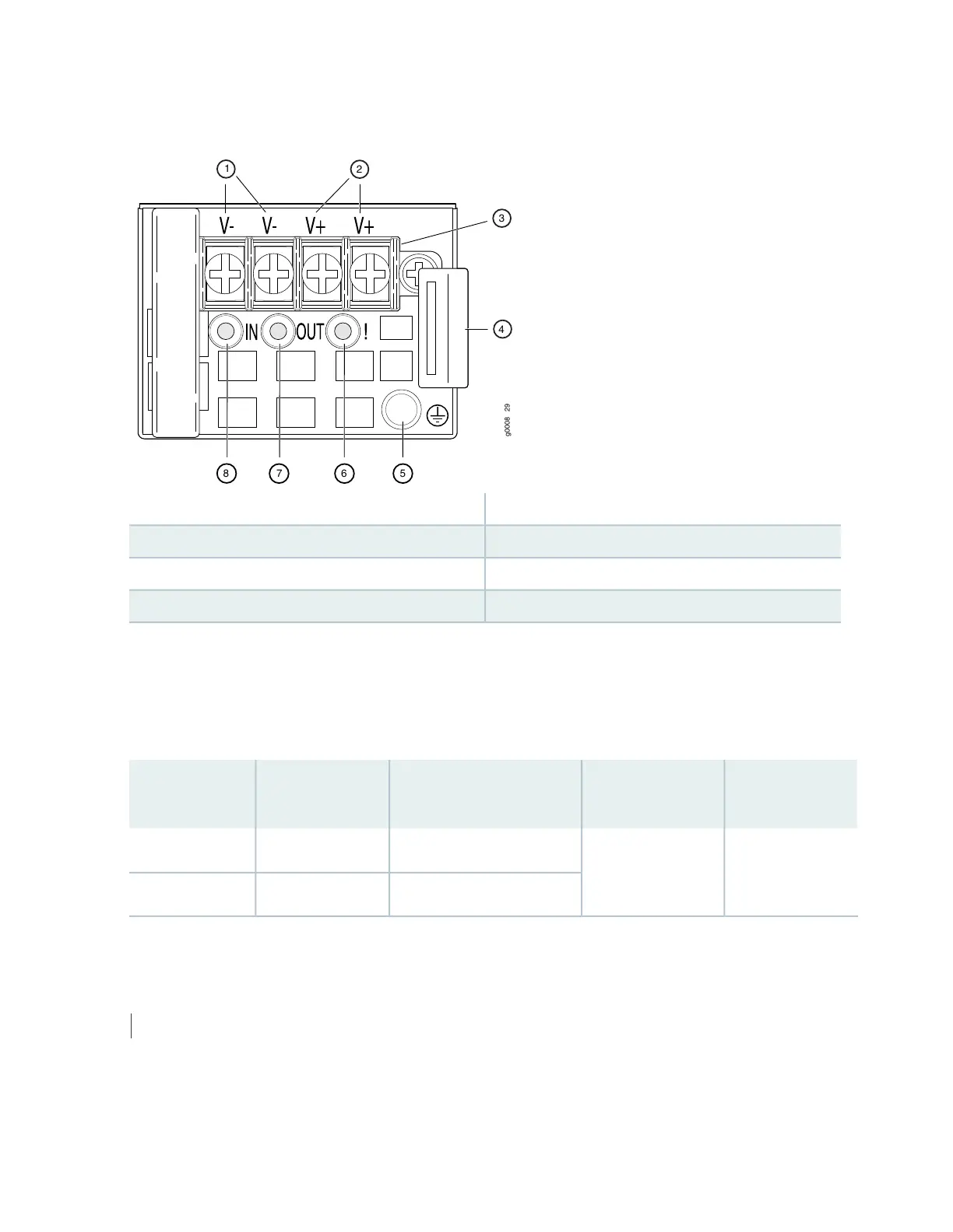
Figure 24: DC Power Supply Faceplate in ACX5000 Routers
5—1— ESD grounding pointShunt negative input terminals (+RTN)
6—2— Fault LEDShunt positive input terminals (–48V)
7—3— Output LEDTerminal block
8—4— Input LEDEjector lever
To avoid electrical injury, carefully follow instructions in “Installing a Power Supply in an ACX5000 Router”
on page 138 and “Removing a Power Supply from an ACX5000 Router” on page 136.
Table 18 on page 71 shows the different power supplies and their direction of airflow.
Table 18: Airflow Direction in ACX5000 DC Power Supplies
Color of Power
Supply Handle
Direction of
AirflowProduct NumberWattageRouter Model
Juniper GoldPort-to-FRUJPSU-650W-DC-AFO650 WACX5048
JPSU-850W-DC-AFO850 WACX5096
SEE ALSO
Connecting DC Power to an ACX5000 Router | 114
71
 Loading...


