E-23
2. CONTROLS, INDICATORS AND CONNECTORS
E-22
2. CONTROLS, INDICATORS AND CONNECTORS
LIGHT
ON
OFF
COUNTER
CTL
TC
UB
RESET
OPERATE/WARNING
MONITOR
SELECT
E
REV FWD
FBATT
H
HM
MSF
REMAIN
AUD LOCK
32k
CH 1
CH 2
48k
PBSLAVE
AUTO OFF DEW
L iRFSERVO
HOLD
SP
WIDE
MENU
OVER
OVER
40 30 20 10 0
dB
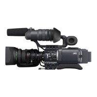
The counter display shows the following 4 types of information.
1.
Tape counter display
The counter display usually functions as a tape counter
(hour, minute, second, frame). It can be switched to a CTL
counter, time code or user's bit display by using the
COUNTER switch. (When the VCR Setup Menu item No.
516 DISPLAY SELECT is set to “TC”.)
• CTL counter: Time between -9 hr. 59 min. 59 sec. 24
frames and 9 hr. 59 min. 59 sec. 24 frames
can be displayed.
* CTL counter indication may also corrupt
at playback of segment which time code
signal is not continuously recorded.
• Time code : Time between 0 hour and 23 hr. 59 min. 59
sec. 24 frames can be displayed.
• User's bit : Hexadecimal number from 0 to F is displayed
in 8 digits.
When the VCR Setup Menu item No. 516 DISPLAY SELECT
is set to “CLOCK”, the date and time are displayed. Set the
COUNTER switch to TC or UB.
TC: Time (Hour, Min., Sec.) is displayed.
UB: Date (Day, Month, Year) is displayed.
• Press the MENU button to switch to the VCR Setup Menu
setting display.
2.
VCR Setup Menu setting display
This display is used when setting the setup menus. After
setting of the setup menus, the tape counter display returns.
For details, see "DISPLAYING AND SETTING VCR SETUP
MENUS" on page 67.
3.
Hour meter display
The hour meter is displayed by selecting the HM group from
the VCR Setup Menu.
The hour meter data refers to the accumulated head drum
running time.
4.
Error code/Alarm display
The error code or alarm indicator is displayed automatically
in case an abnormal condition occurs with the unit.
☞ See “TROUBLES WITH ERROR CODE OUTPUTS” on
page 90.
☞ See “ALARM INDICATIONS” on page 86.
Remaining Battery Power Display
The 7-dot segment bar display shows the remaining battery
power. The lighted segment bars decrease as the remaining
battery power decreases.
• To display the remaining battery power accurately, set the
VCR Setup Menu item No. 396 BATTERY TYPE according
to the type of the battery pack in use.
All segment bars light when a fully charged
battery pack is attached.
The last 2 segment bars and "BATT" start
to blink when the battery is nearly
exhausted. Replace with a fully charged
battery pack.
When the battery capacity has run out, "E"
and "BATT" blink and the unit stops
operation automatically.
EFBATT
E BATT
E BATT
HM
REMAIN
HM
REMAIN
HM
REMAIN
Remaining Tape Time Display
This display shows the remaining tape time (minutes/seconds)
in record and play modes.
• Example: 30 minutes of remaining tape.
• This indicator blinks when remaining tape time is equivalent
to less than 2 minutes.
* An alarm sounds as a warning when remaining tape time is
equivalent to less than 2 minutes in the record mode
• The following display appears when no videocassette is
loaded or during the calculation of remaining tape that takes
place immediately after a videocassette is inserted.
2-6 Counter Display Contents
COUNTER
switch
Counter display
2. 4.
H
3.
H M S F
1.
CTL
TC
UB
H M S F
CTL
TC
UB
CTL
TC
UB
H M S
CTL
TC
UB
CTL
TC
“CTL”
“TC”
“UB”
“TC”
“UB”
UB
4.
CTL counter
Time code
User’s bit
Time display
Date display
Hour Min Sec
Day Month Year
“TC”
VCR Setup
Menu No. 516
DISPLAY SELECT
“CLOCK”
VCR Setup Menu display Error code display
Hour meter display Alarm display
Tape counter display
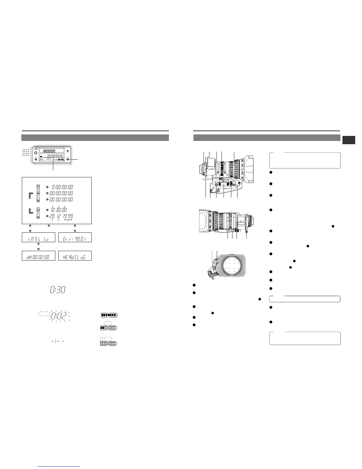
2-7 Lens (optional)
1
FOCUS ring
Manual focus ring.
2
ZOOM lever/ring
This is the manual zoom ring equipped with a zoom lever. To
activate the zoom feature on, turn the zoom mode knob
12
to
position “M”.
3
IRIS ring
Manual Iris ring. To activate the auto iris feature, set the Iris
Mode switch
10
to A.
4
Macro lever
Pull this lever up to enable the rotation of the macro ring.
5
Macro focusing ring (for close-up shooting)
By rotating this ring in the direction of the arrow, the lens be-
comes capable of close-up shooting of very small objects.
Normal focus adjustment and zooming are not available in the
macro mode.
To shoot images in the macro mode, set the focus ring to the
infinite position and the zoom ring to the widest angle position.
A19 × 8.7BW
To adjust the focus of the macro image, rotate this ring in the
direction of arrow until the object is focused.
Note :
The back-focus knob is located close to the macro ring, be
careful not to mistake the back-focus knob for the macro ring.
After the required operation, be sure to return the macro ring
to the normal position.
6
BACK FOCUS ring/fixing screw
For Set-up Back Focus adjustment only.
Secure with the Screw knob after adjustment.
7
[VTR] trigger button
To start shooting push once.
To stop shooting push again.
8
[RET] return video button
The return video signal from the VCR section can be moni-
tored on the viewfinder only while pushing this button.
•
The Viewfinder Status display is not available during this operation.
9
ZOOM servo control lever
Pushing this lever in the W direction makes the lens move
wider.
Pushing this lever in the T direction makes the lens move tighter.
Pushing harder changes the speed of the Zoom. To operate the
servo zoom feature with this lever, set the ZOOM knob
12
to S.
10
IRIS mode switch
A : Activates the auto iris feature.
M : Allows manual iris control.
11
Momentary auto iris button
When the IRIS MODE switch
10
is at M, pushing this button
activates the Auto Iris Function while it is held down only.
12
ZOOM mode knob
S : Servo Zoom mode. Allows operation by the Zoom Servo
Control lever
9
.
M : Manual Zoom mode. Allows zoom control by the Zoom
lever/ring
2
.
13
REMOTE FOCUS control connector
To connect with an optional focus servo unit.
14
ZOOM servo connector
Connect with an optional zoom servo unit.
15
Aspect ratio switching lever
Switches the aspect ratio between 4:3 and 16:9.
Note :
Make sure to switch the lever to the correct position.
16
Rapid zoom setting switch
Quickly sets the zoom to telescopic mode.
For the setting method, refer to the "OPERATION MANUAL"
for the lens.
17
IRIS speed adjusting control
Adjusts the iris operation speed.
Memo :
If the speed becomes too fast, hunting may occur.
To avoid the phenomena described above, perform
adjustment again.
3124
0
$%
^&
!
@#
5
67 8 9
Q
U
I
C
K
Z
O
O
M
A
L
L
O
C
A
T
I
O
N
S
W
I
T
C
H
S
R
E
T
Q
.
Z
V
T
R
M
O
M
Q
.
Z
Q
.
Z
(
A19x8.7BRRM-39
)
A19x8.7BW
1:1.8/8.7-165
FUJIN0N
MADE IN JAPAN
FUJI PHOTO OPTICAL CO.
,
LTD.
by
mm
or RET
QUICK Z
& IF 19x
TV
.
ZOOM LENS
1.82.84
5.6
∞
m
ft
1658040208.7
A
M
WT
FUJI PHOTO
F.f
MACRO
8
C
16
11
8
5.6
O
R
C
M
A
1.5
5
2
7
10
3
5
15
10
30
m
∞
ft
8.7
20
FUJINON
ASPHERIC & IF 19x
TV - ZOOM
 Loading...