E-11
2. CONTROLS, INDICATORS AND CONNECTORS
E-10
2. CONTROLS, INDICATORS AND CONNECTORS
Even when the VCR Setup Menu item No. 246 is set to
DISABLE, the recording level changes slightly when this
control is turned.
can be adjusted more accurately.
9
[TAKE] button
The Super Scene Finder (S.S.F.) function retains the time
code data for IN point and OUT point or CUE point in the
unit's memory.
☞ See “S.S.F. Function on” page 60.
0
Lens mounting ring/Lens lock lever
Hold the lens and use the lever to turn the ring anticlockwise
to release lens.
To mount lens make sure the lens guide pin fits well, and
then turn the ring clockwise until firm.
☞ See "Attaching the Zoom Lens" on page 31.
!
[FILTER] Colour temperature conversion filter
control knob
This knob changes the internal colour temperature filter.
☞ See "Camera Settings" on page 42.
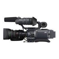
2-1 Front Section (Cont’d)
1
Viewfinder mount base, sliding securing ring
Mount the viewfinder on the base and secure it using the
sliding securing ring.
☞ See "Attaching the Viewfinder" on page 31.
2
[VF] Viewfinder connector (20-pin)
Connect the cable from the viewfinder here.
3
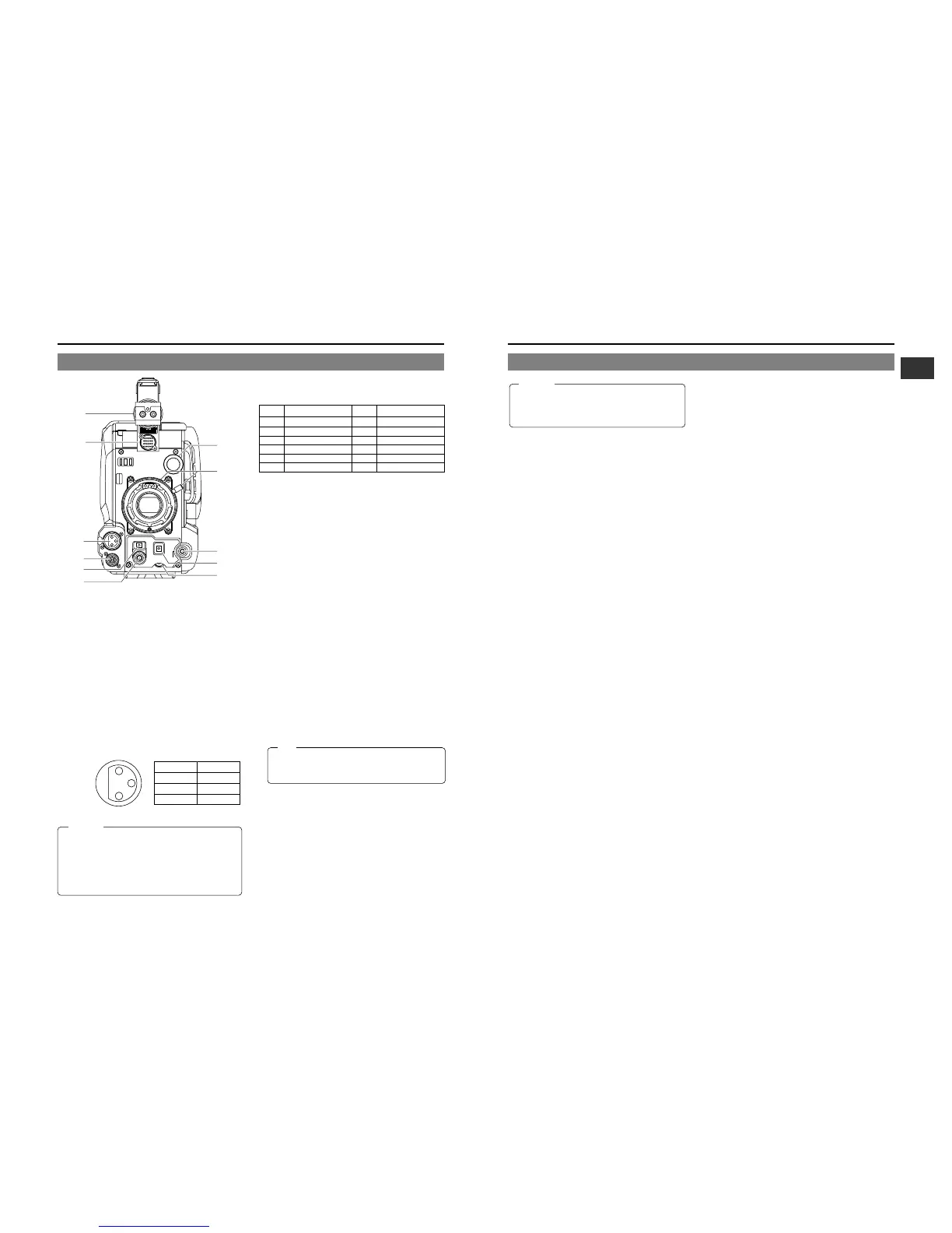
[MIC IN] Microphone input connector (XLR 3-pin)
Balanced 3-pin connector for camera microphone.
• When the camera microphone to be connected is a
phantom microphone or other type of microphone, set
the CAM MIC 48V item on the Camera Setup menu.
☞ See page 77.
• When using a microphone with this connector, set the
AUDIO INPUT switches
7
8
on page 14 to FRONT in
accordance with the audio channel (CH1 or CH2) to be
recorded.
☞ See page 14.
1
2
3
Pin No. Function
1GND
2HOT
3 COLD
2-1 Front Section
AUTO
WHITE
SKIN
AREA
ACCU
FOCUS
TAKE
VTR
ZEBRA
AUDIO
LEVEL CH-1
ON
OFF
VF
1
2
3
4
5
6
7
8
9
0
!
●
The provided microphone is a phantom microphone.
Please confirm that the CAM MIC 48 V item on the
Camera SETUP Menu is set to “ON”.
●
When using a microphone other than a phantom
microphone, first set the CAM MIC 48 V item to “OFF”
before connecting the microphone. Otherwise the
microphone may be damaged.
• As the automatic shutter is activated here, flicker may
appear on the screen depending on the lighting
conditions (such as a fluorescent lamp, etc.)
• This operation is not possible in the LOLUX mode.
Pin No. Function Pin No. Function
1 RET switch 7 IRIS position
2 VCR trigger 8 IRIS A/R INPUT
3 GND 9 EXTENDER position
4
Lens AUTO/MANU control
10 ZOOM position
5 IRIS control 11 —
6 +12V DC 12 —
4
[LENS] Lens control connector
Connect 12-pin lens control cable from lens.
5
[ZEBRA] Switch
When this switch is ON, a zebra pattern is superimposed
on the viewfinder areas having video levels with a luminance
level of over 95%. This pattern can be used as a reference
for manual adjustment of the lens iris.
Zebra patterns are also displayed during color bar display.
* The zebra patterns are only displayed on the viewfinder
screen. The zebra patterns are not generated for the
MONITOR OUT or Y/C OUT output.
☞ See "Zebra Pattern during Manual Adjustment" on
page 80.
• The default value is over 95%. The luminance level can be
changed with the ZEBRA setting in the VF DISPLAY Menu
screen.
☞ See "ZEBRA" item on page 72.
While this switch is pressed to the SKIN AREA side, the
colour tone areas specified with the SKIN DTL ADJUST
item on the ADVANCED PROCESS MENU are indicated in
the viewfinder. The switch returns to the OFF position when
released.
☞ See “How to Use Skin Detail” on page 84.
• The Skin Detail colour tone areas are not indicated while
the VTR playback picture is shown in the viewfinder.
6
[VTR] VTR trigger button (record start/stop button)
Record start/stop can be effected with this button.
(It is interlocked with the VTR trigger button on the lens
section.)
7
[AUDIO LEVEL CH-1] CH-1 recording level control
Adjusts the recording level of the CH1 audio signal input.
Normally, the camera is used with the control set to the
maximum (10) position.
• To use this control, set the VCR Setup Menu item No.
246 FRONT VOLUME ENABLE to "ENABLE".
8
[AUTO WHITE/ACCU FOCUS] switch
AUTO WHITE:
• First, position a white object to occupy 80% of the centre
of the image.
• Setting this switch to the upper position ("AUTO WHT.")
will provide automatic adjustment for white balance.
* It is not activated in preset, full auto shooting, full-time
auto white balance and colour bar modes.
☞ See "White Balance Adjustment" on page 45.
ACCU FOCUS:
• When this switch is set to "ACCU FOCUS" in the lower
position, the lens iris will be forced to open for
approximately ten seconds.
• The depth of field can be reduced and the lens focusing
Note:
CAUTION:
CAUTION:
 Loading...