AUTO
WHITE
SKIN
AREA
ACCU
FOCUS
TAKE
VTR
ZEBRA
AUDIO
LEVEL CH-1
ON
OFF
VF
TALLY
DV
AUDIO IN
CH-1
DC INPUT
EARPHONE
DC OUTPUT
LINE MIC
+48V
ON
CH-2
LINE MIC
+48V
ON
CH-1
CH-2
AUDIO
LEVEL
CH-1 CH-2
AUTO
MANUAL
FRONT
REAR
AUDIO SELECT
AUDIO INPUT
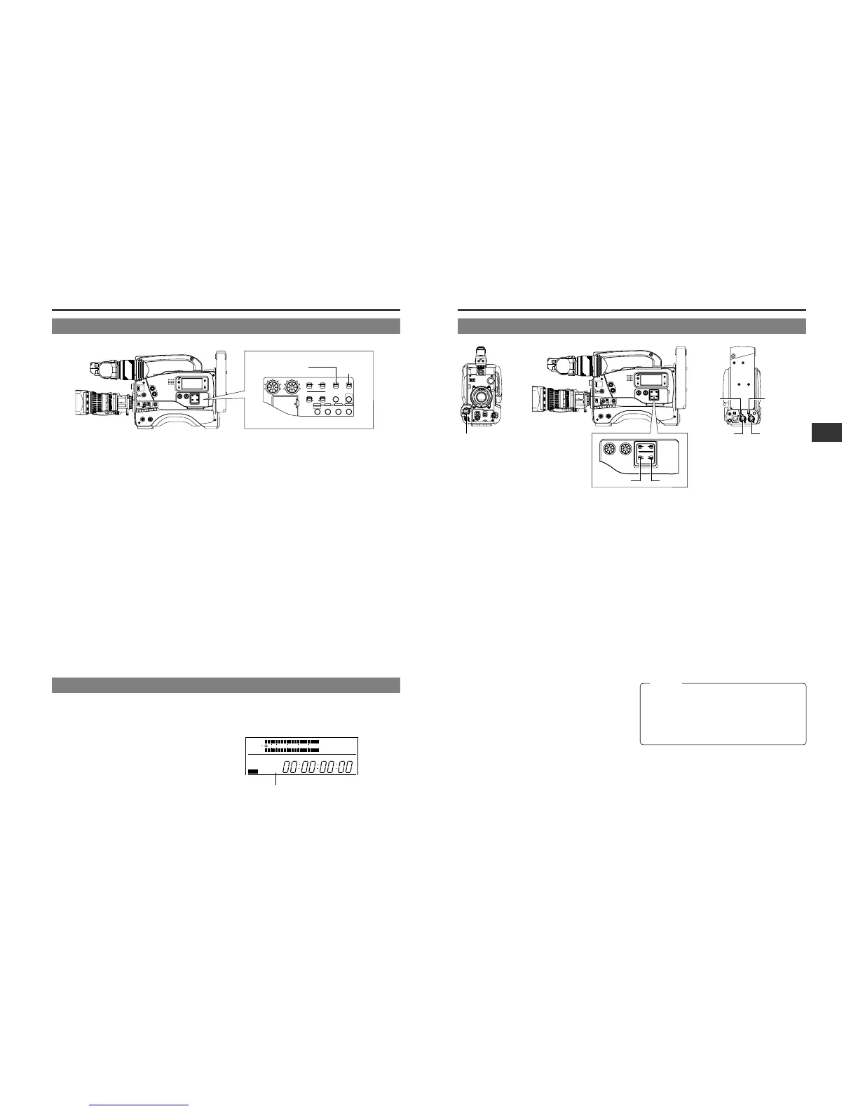
6-8 Audio Input Signal Selection
The GY-DV700W is provided with the microphone connector
on the front section and the two AUDIO INPUT connectors at
the rear section for audio input.
On the other hand, two channels of sound can be recorded on
the tape in digital PCM format.
Using the AUDIO INPUT switch, select for each channel (CH1
and CH2) whether the sound to be recorded should be the
sound from the microphone connector on the front section or
the sound from the AUDIO INPUT connectors on the rear
section.
Selecting the CH-1 channel input sound
Make the selection using the CH-1 AUDIO INPUT switch.
FRONT : The sound from the microphone connector on the
front section is recorded on the CH-1 channel.
REAR : The sound from the CH-1 AUDIO INPUT
connector on the rear section is recorded on the
CH-1 channel.
Selecting the CH-2 channel input sound
Make the selection using the CH-2 AUDIO INPUT switch.
FRONT : The sound from the microphone connector on the
front section is recorded on the CH-2 channel.
REAR : The sound from the CH-2 AUDIO INPUT
connector on the rear section is recorded on the
CH-2 channel.
Selecting the front section's microphone connector
A microphone (phantom microphone, etc.) requiring +48 V
power supply or other type of camera microphone
(monaural) can be connected.
• In accordance with the connected microphone, specify
the phantom microphone or other type of microphone
using the Camera Setup Menu item CAM MIC +48V.
• The reference input level is -60 dBs.
Selection of rear audio input connectors
Select the audio signal input to the AUDIO INPUT connector
using the [LINE/MIC] switch. Make settings for the CH-1
and CH-2 AUDIO IN connectors separately.
LINE : Set to this position when connected to audio
equipment, etc.
The reference input level is +4 dBs.
MIC : Set to this position when using a monaural
microphone.
The reference input level is -60 dBs.
MIC +48 V : Set to this position when a microphone
(phantom microphone) requiring +48 V DC
power supply is connected.
Microphone input
connector
CH-1 AUDIO
LINE/MIC
switch
CH-2 AUDIO
LINE/MIC
switch
CH-1 AUDIO
INPUT
connector
CH-2 AUDIO
INPUT
connector
CH-1 AUDIO
INPUT switch
CH-2 AUDIO
INPUT switch
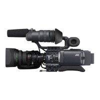
6-6 Switch Settings of the VCR Section
Audio input signal selection
Use the AUDIO INPUT switch to select whether the sound
recorded on audio channel 1 or 2 is the sound from the
microphone connector on the front section or the sound from
the AUDIO INPUT connector on the rear section.
☞ See page 47.
Audio recording level adjustment selection
Select "AUTO" or "MANUAL" for the recording level
adjustment mode for each audio channel.
☞ See page 48.
VCR Setup Menu setting
● REMOTE SELECT
Confirm that "LOCAL" is selected if you want to operate on
the GY-DV700W only.
● BACK TALLY MODE
Select the lightning pattern of the BACK TALLY lamp.
● LOW CUT IN
For each audio input connector, select whether or not the
lower frequency components of the audio signal are cut.
Set to this position to eliminate the wind noise of the
microphone.
● SAMPLING RATE
Select the sampling rate for audio recording (48 kHz or 32
kHz).
● FRONT VOLUME ENABLE
Set whether or not the front section's audio volume control
should be used. The front section's audio volume control only
affects the CH1 audio channel.
● LONG PAUSE TIME
Select the time (in minutes) until the GY-DV700W enters the
tape protection mode (drum rotation stops) when the record-
pause mode is continued for long time.
● SSF MODE
Select the mode of the S.S.F. (Super Scene Finder) function.
S.S.F. function: Stores the time code of desired scenes or
cue points in the unit's memory.
☞ See “S.S.F. function” on page 60.
● DISPLAY SELECT
Select the counter display (time code or date/time indication)
when the COUNTER switch is set to “TC” or “UB”.
Setting the time code recording function
The GY-DV700W records EBU-standard time code during
recording. Set the switches according to applications.
● To record a time code as set in the built-in time code
generator:
• Set the PRESET/REGEN switch to PRESET.
• Set the REC/FREE switch.
If it is required to record continual time codes across different
scenes, set the switch to REC.
● To record a time code in continuation of the existing time
code on the tape:
• Set the PRESET/REGEN switch to REGEN.
• Set the VCR Setup Menu item No. 302 BACK SPACE to
“STANDARD”.
For details on the time code operations including time code
presetting, see "TIME CODE OPERATION" on page 56.
LIGHT
ON
OFF
COUNTER
CTL
TC
UB
RESET
OPERATE/WARNING
MONITOR
SELECT
STATUSSHUTTER
MENU
FILTER
1 3200k
2 5600k+1/8ND
3 5600k
4 5600k+1/64ND
POWER
NG
G
A
IN
O
U
T
P
U
T
W
H
T
.B
A
L
V
T
R
ON OFF
ALARM
MONITOR
S
A
V
E
S
T
B
Y
H
M
L
B
A
R
S
C
A
M
A
U
T
O
K
N
E
E
P
R
S
T
A
B
O
N
O
F
F
CH-1
CH-2
AUDIO
LEVEL
AUTO IRIS LOLUX
BACK L
NORMAL
SPOT L
STRETCH
NORMAL
COMPRESS
FULL AUTO BLACK
C
TC GENERATOR
FREE
REC
PRESET
REGEN
CH-1
CH-2CH-1
CH-2
CH-1 CH-2
CONTINUE MENU
PRESETADVANCESHIFTHOLD
AUTO
MANUAL
FRONT
REAR
DATA SET
SELECTITEMGROUP
AUDIO SELECT
AUDIO INPUT
AUDIO
LEVEL
LITHIUM BATT.
PRESET/REGEN switch
REC/FREE
switch
When connecting a component that does not require
+48 V power supply, make sure that the LINE/MIC switch
is not set to MIC +48V.
When using the microphone on the front section, set the
Camera SETUP screen item “CAM, MIC, 48V” to “OFF”.
Neglecting this could cause damage to the connected
component.
6-7 Recording Mode Selection (16:9 Picture or 4:3 Picture)
Select whether the recording mode should be WIDE (16:9
picture) or NORMAL (4:3 picture).
Use either of the following methods to make the selection.
Make the selection using the ASPECT RATIO item on
the camera OPERATION MENU screen.
☞ See page 73.
Or,
Use the aspect ratio switching lever on the lens section.
☞ See page 23.
* If the settings made using the above methods are not
identical, the setting of the lens’ switching lever will have
priority.
WIDE indicator
CAUTION:
 Loading...