E-25
2. CONTROLS, INDICATORS AND CONNECTORS
E-24
2. CONTROLS, INDICATORS AND CONNECTORS
STATUSSHUTTER
MENU
POWER
NG
GAIN
OUTPUT
WHT.BAL
VTR
ON OFF
ALARM
MONITOR
S
A
V
E
S
T
B
Y
H
M
L
B
A
R
S
C
A
M
A
U
T
O
K
N
E
E
P
R
S
T
A
B
O
N
O
F
F
AUTO IRIS LOLUX
BACK L
NORMAL
SPOT L
STRETCH
NORMAL
COMPRESS
FULL AUTO BLACK
FILTER
1 3200k
2 5600k+1/8ND
3 5600k
4 5600k+1/64ND
STATUS
button
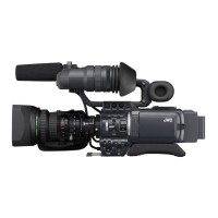
2-8 1.5-Inch Viewfinder (optional)
BATT ALARM
REC
BATT
Lamp
REC/ALARM
Lamp
The viewfinder has two LED indicators below the screen. These
LEDs light or blink to indicate the present status of the camera
or the VCR.
●
[BATT] battery lamp
This lights red when the battery voltage becomes too low for
operating the camera.
●
REC/ALARM lamp
This lights or blinks green under the following circumstances.
Steady green : During recording.
Blinks green : • While the GY-DV700W switches from
record-pause to recording.
• Immediately before the tape is running out
or when it has run out.
• When an error occurs in the GY-DV700W.
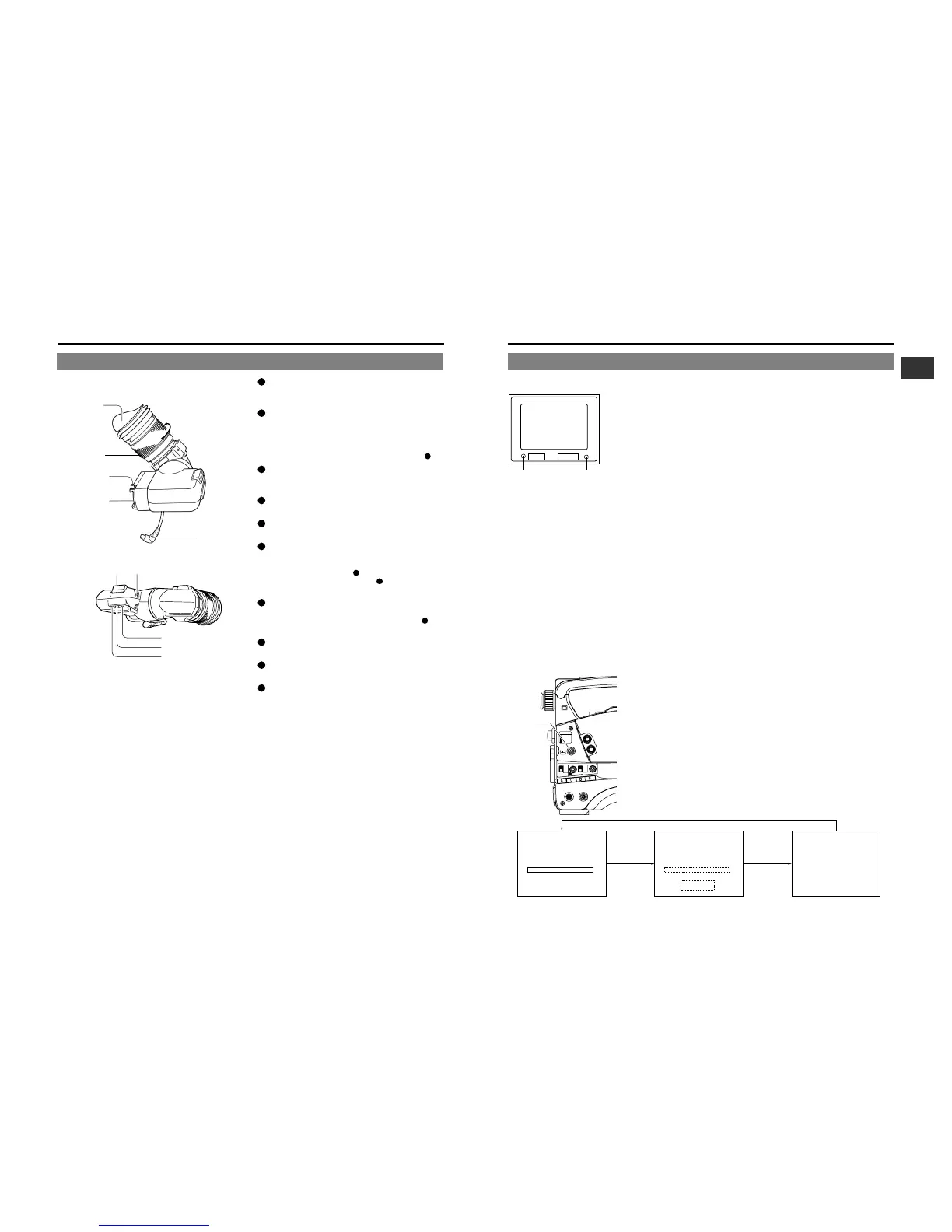
2-9 Indications in Viewfinder
WARNING LED INDICATORS INSIDE THE VIEWFINDER
VIEWFINDER SCREEN DISPLAY
The following indications are displayed on the viewfinder screen. (However, this information is not displayed while the VCR section
is playing back a tape.)
Status screens (screens for use in checking the current camera settings)
Alarm message display
Safety zone display
Setting screen (screen for use in the camera and VCR setup)
Auto white balance display
Shutter speed display
Status Screens
Press the STATUS button during normal screen display to show one of the status
screens in the viewfinder. One of the three status screens will be displayed every
time the button is pressed.
ACCU - FOCUS
G
F
I
SD
B
ACCU
M909
-FOCUS
G
F
I
F5.6
STBY 4V21.<60
B
CH1 ----+--
CH2 ----+--
SCENE F I LE
WH I T E B A L A
A
FILTER
SHUTTER 1/10
3.2K
00
GA I N 6 d B
I R I S LEVE L NORMAL
I R I S DE T EC T NORMA L
FUL L AUTO OFF
REC T I ME < 6 0
SD
Status 0
Status 1 Status 2
1
Eyepiece
Blocks light to viewfinder screen and holds eye optics.
The Eyepiece can be opened to view the screen directly.
2
Eyepiece focusing ring
Rotate this ring to adjust the viewing angle.
Be sure to adjust this ring because the viewing angle af-
fects the lens focus adjustment.
To perform more reliable focus adjustment, it is recommend-
ed to turn on the contour with the PEAKING control
8
.
3
Stopper screw
This stopper screw prevents the viewfinder from coming off
the camera.
4
Viewfinder shoe
Attaches to the Viewfinder Mount base on camera.
5
Cable
Connect to camera viewfinder connector.
6
Tally switch
Set this switch to off if you do not want to inform the subjects
by the Tally light that they are being recorded.
ON : Lights the Tally lamp
7
during recording.
OFF : Does not light the Tally lamp
7
.
However, the REC lamp at the eyepiece will not turn off.
7
Tally light
Lights when recording is in progress.
The light does not come on when the Tally Switch
6
is at
“OFF”.
8
[PEAKING] peaking (contour) control
Rotate to adjust the contour of the viewfinder screen image.
9
[CONT] contrast
Controls the level of Viewfinder contrast.
10
[BRIGHT] brightness
Controls the level of Viewfinder brightness.
VF-P116W
2
3
5
67
8
9
0
4
1
 Loading...