E-31
3. BASIC SYSTEM CONNECTIONS AND ADJUSTMENTS
E-30
3. BASIC SYSTEM CONNECTIONS AND ADJUSTMENTS
4.
3
2.
1.
1.
Loosen the mount ring.
2.
Connect the cable connector.
3.
Attach the lens with its pin aligned with the hole in the mount.
4.
Tighten the mount ring.
Be sure to tighten the mount ring completely. Incomplete
tightening may result in the lens dropping off or disturbed
back focus.
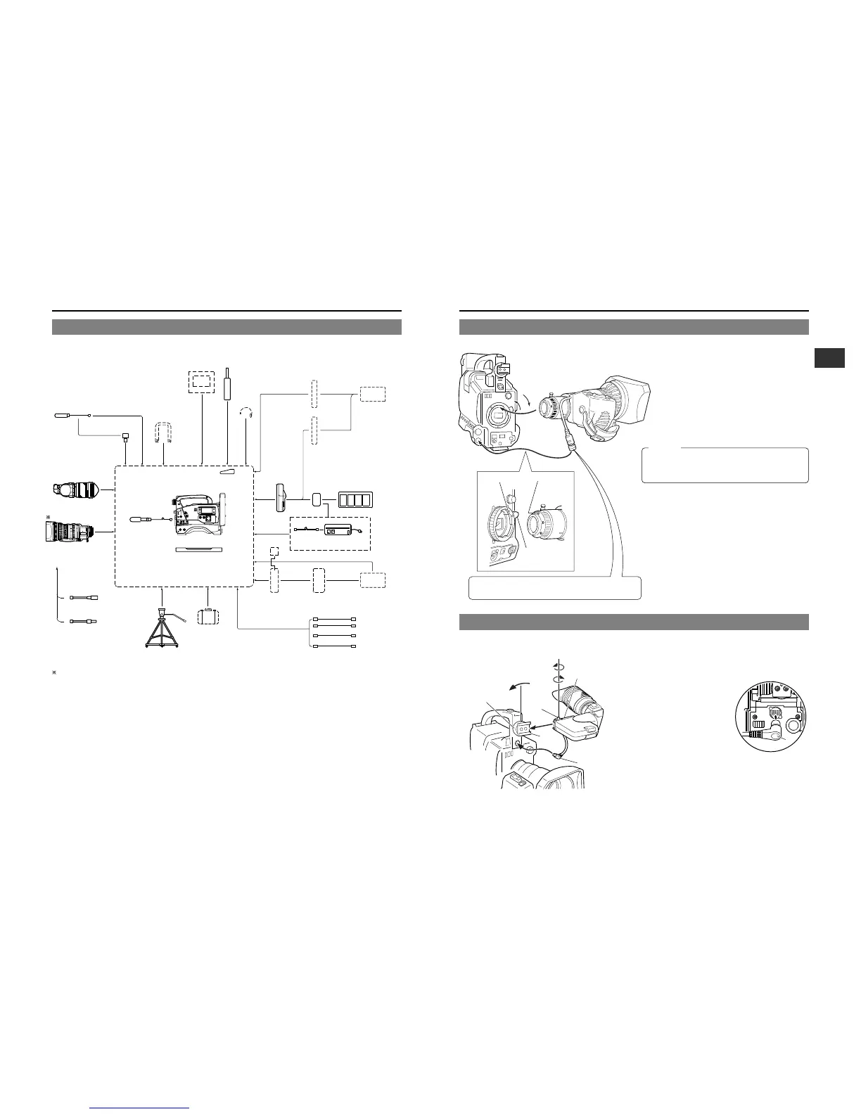
3-2 Attaching the Zoom Lens (optional)
3-3 Attaching the Viewfinder (optional)
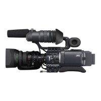
For information on connection with the individual attachments, refer to the page explaining the respective connection methods.
3-1 Basic System
When 4:3 lens is mounted on the GY-DV700W.
1 When used in the 4:3 mode, approximately 20% of the image angle is shifted to the telephoto-side.
2 To use the 16:9 mode, change the setting by means of the ASPECT RATIO item in the GY-DV700W’s camera OPERATION
MENU.
1.
4.
2.
3.
5.
Sliding
securing ring
Mounting guide
Stopper
screw
Connector
Viewfinder
mount
base
1.
Loosen the stopper screw.
2.
Attach the viewfinder with its guide aligned with the shoe.
3.
Connect the cable
connector as shown in
the figure on the right.
Hole
Pin
Mounting
CAUTION:
When unplugging the cable connector, first remove the lens
itself. Then grasp this portion and pull straight out.
 Loading...