E-69
12. SETUP MENU
E-68
12. SETUP MENU
Selection of amount of back space for recording pause.
STANDARD
: Normally use this setting.
QUICK : Compared to STANDARD, the back space
becomes approximately 0.4 seconds
shorter.
Use this setting when you want to start
shooting quickly. However, in the REGEN
mode, the time code may not continue.
To select the time (minutes) before the save mode (drum
head rotation stopped) is engaged when
the record-pause, still or stop condition
continues.
3MIN : 3 minutes
30MIN : 30 minutes
* When used in a cold environment, the setting will be
3 minutes regardless of the setting.
To be set in accordance with the used battery back type.
12V : Choose this setting when using 12V battery
(12V DC Flat shape type).
13.2V : Choose this setting when using 13.2V battery
(Anton-Bauer Trimpack 13, Propack 13,
Magnum 13, Compack 13).
14.4V : Choose this setting when using 14.4V battery
(Anton-Bauer Trimpack 14, Propack 14,
Magnum 14, Compack 14).
Selection of the S.S.F. (Super Scene Finder) mode.
S.S.F. function:While recording, the time code data of a
desired recorded scene is stored in the unit's memory
when the TAKE button on the front section is pressed.
Settings cannot be changed during recording or SAVE
mode.
OFF : S.S.F. function is not available.
CUE MODE : Selects the CUE mode.
When the TAKE button is pressed, the
time code data of the scene recorded
at that point is stored in the memory.
MARK MODE: Selects the MARK mode.
When the TAKE button is pressed the
first time, the time code of this point is
stored as start point of the scene. When
the TAKE button is pressed the second
time, the time code of this point is stored
as ending point of the scene.
For details on the S.S.F. function, see page 60.
• When the VCR Setup Menu item No. 398 S.S.F. MODE
is set to CUE or MARK, the time code generator’s
running method is internally set to the REGEN mode.
To set whether user’s bits also should be slave-locked
when slave-locking with external time code generator.
TC&UB : User’s bits also slave-locked
TC
: User’s bits are not slave-locked
Selection of the appearance of the counter display when
the COUNTER switch is set to “TC” or “UB”.
TC : The time code is displayed.
CLOCK: The date/time is displayed.
302: BACK SPACE
b-SP
307: LONG PAUSE
TIME
LGPt
396: BATTERY TYPE
bAtt
398: SSF MODE
SSF
403: U-BIT SLAVE
UbSc
516: DISPLAY
SELECT
dSP
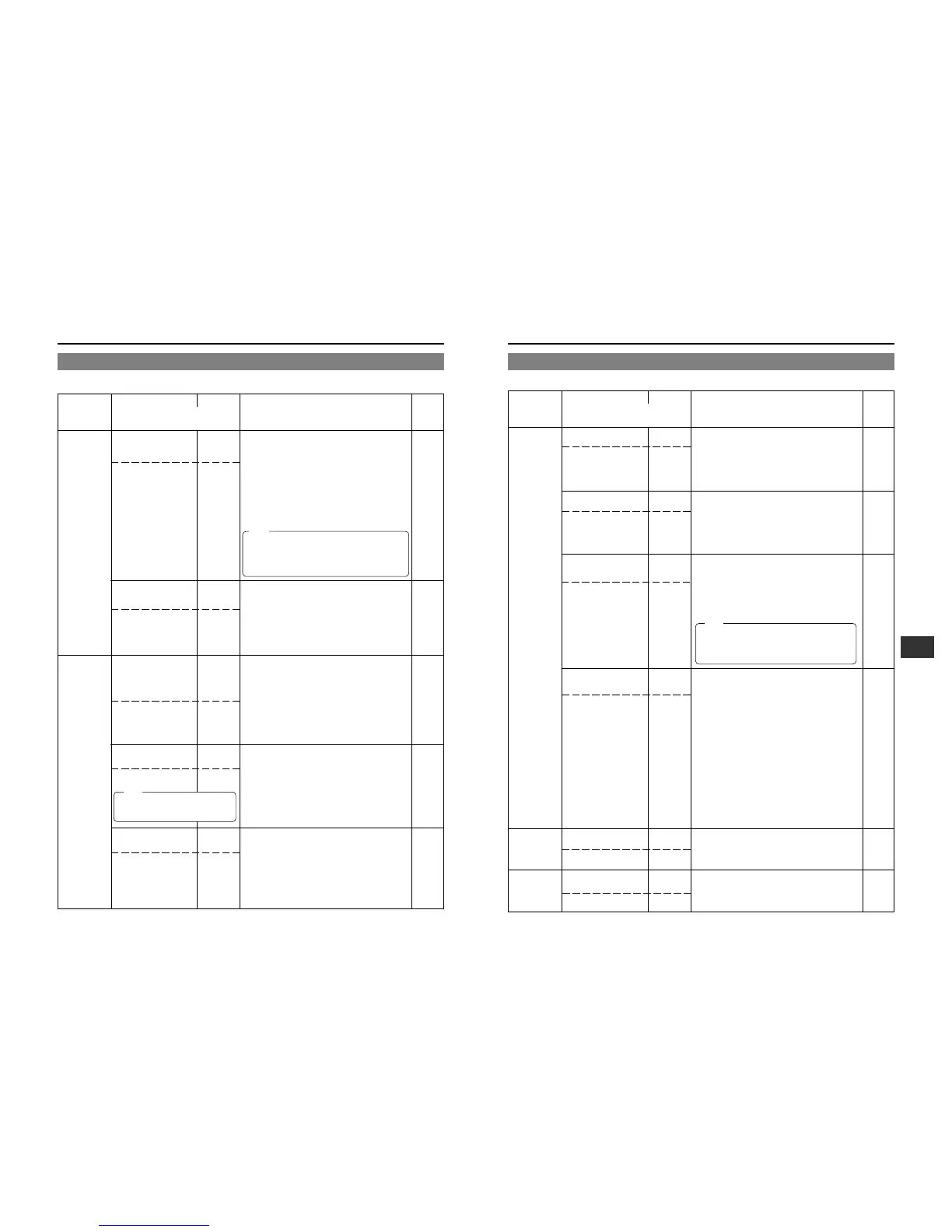
12-1 VCR Setup Menu (Cont'd)
SYSTEM
TIME CODE
ON
SCREEN
STANDARD
QUICK
St
gU
3MIN
30MIN
03
30
12V
13.2V
14.4V
12
13
14
OFF
CUE MODE
MARK MODE
oF
cU
nr
TC&UB
TC
on
oF
TC
CLOCK
tc
cL
STAND-
ARD
30MIN
12V
OFF
TC
TC
Group
Item
Setting
Contents
Factory
Value
Setting
Upper row: Viewfinder display
Lower row: Counter display indication
VCR SETUP MENU CONTENTS
SERVO
/SYSTEM
AUDIO
050:
REMOTE SELECT
rnSL
082:
BACK TALLY MODE
rtMd
244: LOW CUT
LctF
245: SAMPLING RATE
snPL
246: FRONT VOLUME
ENABLE
FruL
LOCAL
IEEE1394
RS232C
Lc
IE
23
OFF
ON
BLINK
oF
on
bL
OFF
CH1
CH2
CH1 &
CH2
oF
01
02
on
32K
48K
32
48
DISABLE
ENABLE
oF
on
LOCAL
BLINK
OFF
48K
ENABLE
Group
Item
Setting
Contents
Factory
Value
Setting
Upper row: Viewfinder display
Lower row: Counter display indication
12-1 VCR Setup Menu (Cont'd)
• If this setting is neglected, the unit’s display of
remaining of battery power and generation of
battery alarm will not work correctly.
• This setting is valid when battery pack is used. It
is invalid when a DC power supply is used.
Note:
The setting of this item can only be
changed in the stop mode or when a
cassette is not loaded.
Note:
Selection of the method for remote control of the VCR.
LOCAL : Choose this setting when the VCR should
be controlled using the operation buttons
on the GY-DV700W only.
IEEE1394 : Choose this setting when the VCR should
be remote controlled from a DV connector
equipped video component connected to
the DV connector on the rear section of the
GY-DV700W.
RS232C : Choose this setting for control by means of
the VCR remote control signal from the VTR
REMOTE connector on the GY-DV700W.
Note:
• The operation buttons on the GY-DV700W remain
effective even when set to IEEE1394 or RS232C.
• When the REMOTE SELECT item is set to IEEE1394
or RS232C, ASPECT RATIO will be fixed and “FIX” is
displayed.
Selection of the lighting pattern of the BACK TALLY lamp
on the rear section during recording.
OFF : The lamp is always off.
ON : The lamp lights during recording. It remains
off until the VTR trigger button is pressed
to start the recording.
BLINK : The lamp lights during recording. It blinks
when the VTR trigger button is pressed to
start the recording.
To select whether or not the low frequencies of the audio
signal from the audio input connectors are cut. Set to
ON to reduce the wind noise of the microphone.
OFF : The CH1 and CH2 low frequencies are not
cut.
CH1 : Only the low frequencies of the audio signal
input to the CH1 channel are cut.
CH2 : Only the low frequencies of the audio signal
input to the CH2 channel are cut.
CH1& CH2
: The low frequencies are cut for both CH1
and CH2.
To select the sampling rate for digital PCM audio
recording.
32K : Digital recording occurs with 12-bit, 32 kHz
sampling
48K : Digital recording occurs with 16-bit 48 kHz
sampling.
*
The DV format offers recording tracks for up to 4
channel when recording using 12-bit, 32 kHz sampling.
The GY-DV700W records two of these tracks. The GY-
DV700W does not allow after-recording.
To select whether or not the front section recording level
control should be operative. The front section recording
level control only affects the audio signal recorded on
CH1.
DISABLE : Use of the front section recording level
control is disabled.
ENABLE : Use of the front section recording level
control is enabled.
* The CH-1 recording level control on the side section
works regardless of the setting.
 Loading...