3-6 Attaching the Tripod Base (provided)
Use the provided tripod base to place the camera on a tripod.
1.
Attach the tripod base on the tripod by using the hole that
balances the unit most optimally.
2.
While pushing the safety lever, pull the lock lever toward
the front until the front mount clip clicks into place.
3.
Place the unit on the tripod base by aligning the rear base
mount of the unit with the pin on the tripod base.
4.
Push the unit from the upward direction and slide it toward
the front so that the front base mount of the unit is locked
by the front mount clip of the tripod base as it clicks into
place.
• The front base mount may be locked while the pin of the
tripod base is not inserted into the hole on the rear base
mount of the unit. Therefore, after mounting, make sure
that these parts are engaged properly.
• When moving the unit mounted on a tripod, any impact
or vibration should be avoided as this may cause the unit
to become detached and to drop from the tripod.
Be sure to remove the unit from the tripod before
transporting it.
Connecting the provided microphone to the viewfinder.
The provided microphone is a phantom microphone.
1.
Loosen the stopper screw on the viewfinder.
2.
Attach the microphone to the attachment guide on the
viewfinder as illustrated.
3.
Confirm that there is no gap between the microphone and
the viewfinder, and then tighten the stopper screw.
4.
Tighten the microphone screw. The microphone should be
firmly attached.
5.
Connect the cable from the microphone to the MIC IN
connector on the front section of the camera.
6.
Secure the microphone cable using the cable clamp located
on the front of the camera.
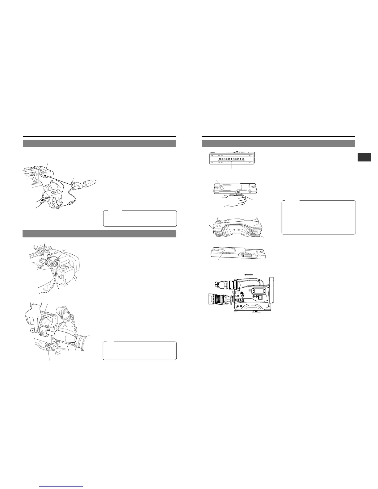
3-4 Attaching the Microphone (provided)
3-5 Attaching the Microphone (optional)
Provided Microphone
With the optional KA-A50 microphone holder, the optional
microphones MV-P615 (Phantom microphone) can be used.
Attaching the Microphone with KA-A50
1.
Secure the microphone holder with 2 screws.
2.
Turn the small knob located on the outer side of the
microphone holder anticlockwise to loosen it, and loosen
the large knob located on the inner side in the same way.
Rotate the large knob fully anticlockwise to open the holder.
3.
Attach the microphone to the microphone holder so that
the microphone does not interfere with the cassette cover.
4.
Set the microphone holder so that the height is level, and
tighten the inside and outside knobs to secure the
microphone.
5.
Connect the microphone cable to the MIC IN input
connector.
• When the microphone is connected to CH-1 AUDIO or
CH-2 AUDIO connector on the rear panel, set the CH-1
or CH-2 Audio select switch according to the microphone
used.
6.
Secure the microphone cable using the cable clamp located
on the front of the camera.
7.
Make sure to perform the correct settings for use of a
phantom microphone.
☞ See “CAM MIC +48V” on page 77.
• When the light mounted on the camera is used at the
same time, if the microphone in use has a long sound
collecting section (ultra-directional type, etc.), the
microphone's shadow may influence the image.
KA-A50
Microphone holder
MV-P615
Microphone cable
MIC IN connector
2.
4.
1.3.
5.
2.4.
1.
3.
When this microphone is attached, the range that the
viewfinder can be moved to the left will be reduced. Please
purchase a separately sold microphone if you prefer to
observe through the viewfinder using your left eye.
CAUTION:
 Loading...