E-64
11. USING EXTERNAL COMPONENTS
E-65
11. USING EXTERNAL COMPONENTS
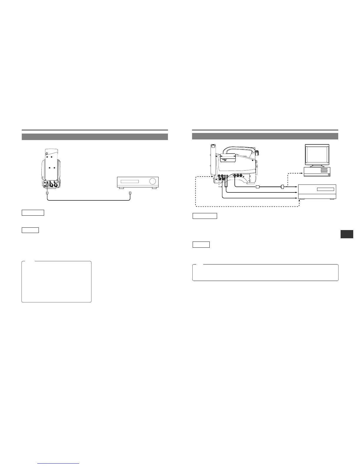
11-2 Connecting a PC
Connections
Connect the GY-DV700W's VTR REMOTE connector to the RS-232C connector on the PC or the non-linear editing controller
using the TTL ⇔ RS-232C converter cable.
Or connect the GY-DV700W’s DV connector and the DV connector of the non-linear editing controller using a DV cable.
For compatible non-linear editing controller, consult with your JVC dealer.
Settings
• To remote control the PC or non-linear editing controller by means of RS-232C, set the VCR Setup Menu item No. 050 REMOTE
SELECT to "RS232C". ☞ See page 68.
• To remote control the GY-DV700W’s VCR using the DV connector’s IEEE1394 option, set the VCR Setup Menu item No. 050
REMOTE SELECT to “IEEE1394”. ☞ See page 68.
The S.S.F. data stored in the memory of the unit or at the beginning of the tape can be output through the VTR REMOTE terminal.
☞ See page 63.
• When a cable is connected to the VTR REMOTE connector, the VTR Setup Menu is not displayed in the viewfinder. Make
settings on the VTR Setup Menu while the cable is not connected.
• When a cable is connected to the VTR REMOTE connector, the VCR operation mode will not be displayed correctly on the
Status 1 screen in the viewfinder.
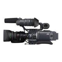
11-1 Connecting a Video Component with DV Connector
Connection
Connect the DV connector on the GY-DV700W to the DV
connector on the video component using the DV cable.
Settings
Recording the playback image or audio of the GY-DV700W
on the video component with DV connector
• To remote control the playback operation of the GY-DV700W
from the video component with DV connector, set the VCR
Setup Menu item No. 050 REMOTE SELECT to "IEEE1394".
☞ See page 68.
TALLY
DV
AUDIO IN
CH-1
DC INPUT
EARPHONE
DC OUTPUT
LINE MIC
+48V
ON
CH-2
LINE MIC
+48V
ON
Rear section of GY-DV700W
DV connector
DV cable
DV connector
Video component with DV Connector
Note:
• When the DV cable is connected for communication with
another component, to stabilize the IEEE1394 output
signal, the STILL mode is activated for a few seconds
and the LED of the STILL button on the top section of
the GY-DV700W lights when the mode is switched to
PLAY or x1 FWD search.
* The x1 FWD search only works during IEEE1394
control or RS-232C control.
• The operation method differs with the characteristics and
specifications of the connected equipment. Even if
connection is possible, operation or data communication
may sometimes be impossible to perform.
Memo:
VTR
REMOTE connector
TTL RS-232C
converter cable
(Optional VC-P893)
AUDIO OUT
DV connector
AUDIO IN
VIDEO IN
PC
RS-232C
RS-232C
Non-linear editing controller
DV connector
MONITOR
OUT
connector
TC OUTTC IN
VTR
REMOTE
SYNC IN
MIC IN
LENS
TEST OUT
Y/C OUT MONITOR OUT
LINE OUT
CH-1 CH-2
PUSH
DV CAMCORDER
GY-DV700
W
 Loading...