3
English
English
Connections
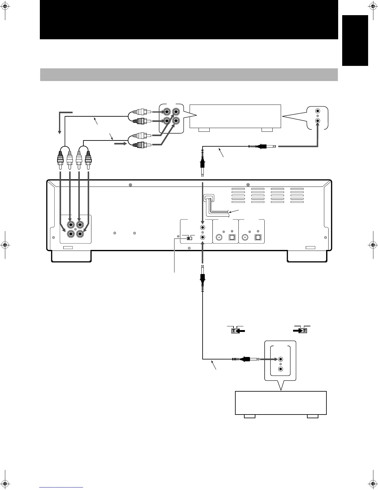
Do not turn on the power until all connections have been completed.
Use the accessory pin cables to connect this unit’s LINE terminals with those for the TAPE/CD/VCR on the receiver, etc.
Analog Connections
TAPE
/CDR
IN
(PLAY)
OUT
(REC)
COMPU LINK
-
4
SYNCHRO
COMPU LINK
-
3
SYNCHRO
LINE
COMPU LINK
-
4
(SYNCHRO)
DIGITAL IN
COAXIAL OPTICAL
DIGITAL OUT
MODE
CDR TD
IN REC
( )
OUT PLAY
LEFTLEFT
RIGHTRIGHT
( )
COAXIAL OPTICAL
CDR
MODE
TD
Recording signals
(line input)
Accessory pin cables
Playback signals
Amplifier, receiver etc.
made by JVC
Selecting a COMPU LINK-4 MODE switch
position
• When connected with
CDR input/output
terminals of the amplifier
or receiver
• When connected with
TAPE input/output
terminals of the amplifier
or receiver
• For more details regarding COMPU LINK, see page 43.
CD player, cassette deck or
other component made by JVC
Note
• The COMPU LINK-4 feature is only supported by other JVC
products also equipped with the COMPU LINK feature. Please
check the manual(s) of your JVC product for compatibility.
• Before selecting the COMPU LINK-4 MODE switch position
(CDR or TD), turn off the power and disconnect the power cord
from the wall socket. The function cannot be reset while the
power is on. Alternatively, if the COMPU LINK-4 MODE
switch position (CDR or TD) is changed while the power is on,
turn off the power, disconnect the power cord and then recon-
nect it. The new setting will be read into the system when power
to the main unit is turned back on.
• Misconnections can be avoided by using the white plugs on the
accessory pin cables for the LEFT channel and the red plugs for
the RIGHT channel.
• Insert the plugs all the way in. Incomplete connections may
cause noise.
• When plugging the power cord into the AC outlet, be sure to
match the width of the plug blades with the outlet.
CDR
MODE
TD
to AC wall socket
Accessory
connecting cable
(with black plugs)
Mode switch
Optional connecting cable
Main Unit
Power
cord
XL-R5010BK.book Page 3 Monday, June 4, 2001 11:40 AM
 Loading...