7.4.2 Make the grid connection
Make the grid connection
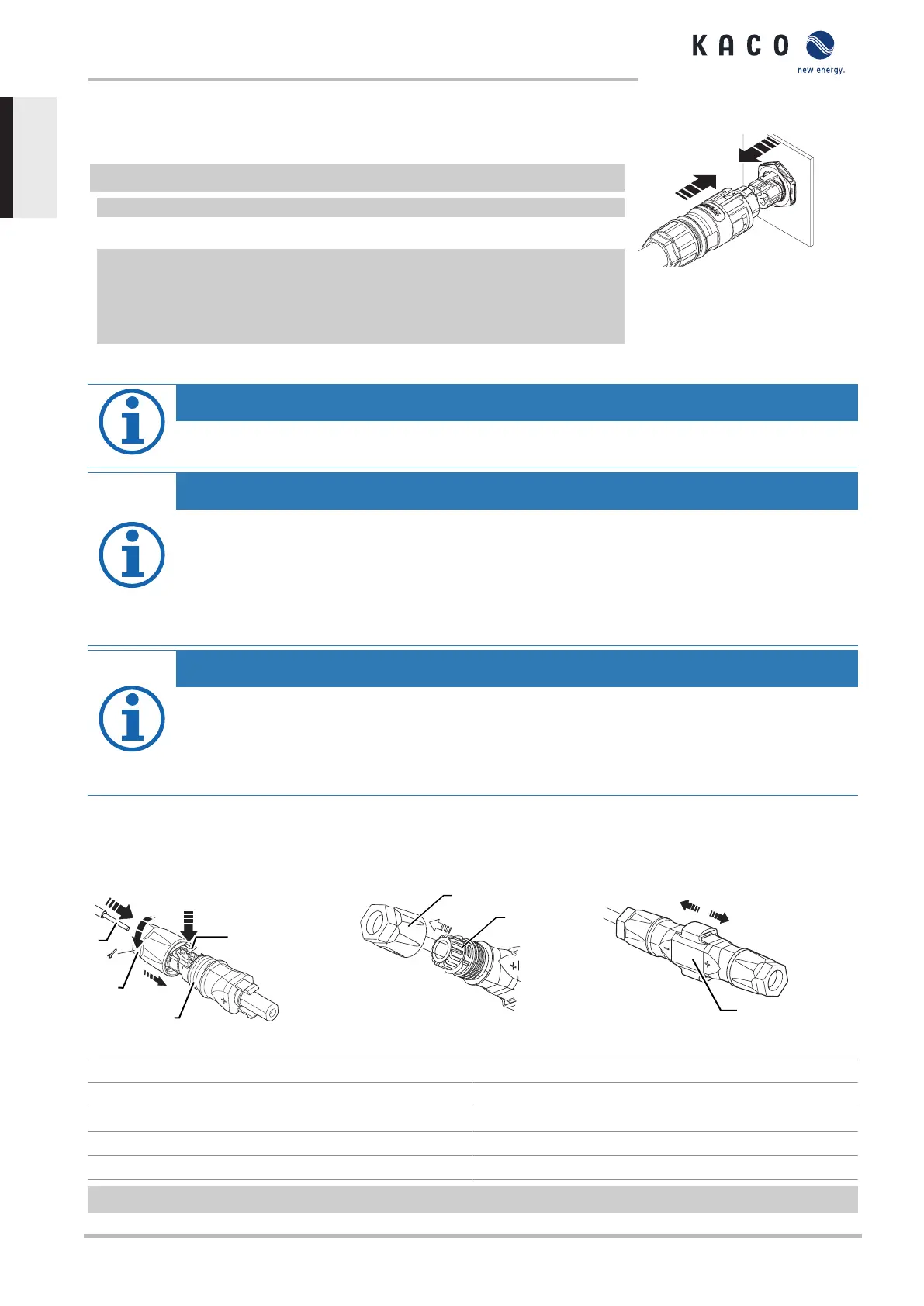
↻ AC connection plug configured correctly.
1 Insert the AC connection plug into the device connector on the device.
ð NOTE:The AC connection is secure when an audible click is heard.
2 Lay the cables correctly and in accordance with the following rules:
- Lay the cables around the device with a minimum clearance of 20 cm
- Never lay cables over semiconductors (cooling bodies)
- Excessive bending force may negatively impact the protection rating. Lay the
cables with a bending radius of at least 4 times the cable diameter.
» The device is connected to the power grid.
Fig.17: Engage the AC connector
with the device connector
NOTE
An AC-side disconnection unit must be provided during the final installation stage. This disconnecter mech-
anism must be installed so that it can be accessed at any time without obstruction.
NOTE
If a residual current circuit breaker is necessary due to the installation specification, a type A residual cur-
rent circuit breaker must be used.
If the type A is used, the insulation threshold must be set to greater than/equal to (≥) 200kOhm in the
“Parameters” menu Menu.
For questions regarding the appropriate type, please contact the installer or our KACO new energy cus-
tomer service.
NOTE
When the line resistance is high, i.e. long cables on the grid side, the voltage at the grid terminals of the
device will increase in feed-in mode. If the voltage exceeds the country-specific grid overvoltage limit
value, the device switches off.
› Ensure that the cable cross-sections are sufficiently large or that the cable lengths are sufficiently
short.
7.5 Connect PV generator to device
7.5.1 Configuring the DC plug connector
Fig.18: Insert wires
Fig.19: Slide insert into sleeve
Fig.20: Check fastening
Key
1 Wire for DC connection 5 Cable fitting
2 Spring 6 Contact plug
3 Insert 7 Coupling
4 Sleeve
↻ Connection area opened.
KACO blueplanet 3.0 TL3 KACO blueplanet 4.0 TL3 KACO blueplanet 5.0 TL3 KACO blueplanet 6.5 TL3 KACO
blueplanet 7.5 TL3 KACO blueplanet 8.6 TL3 KACO blueplanet 9.0 TL3 KACO blueplanet 10.0 TL3
Page 20
EN
 Loading...


