TECHNICAL DESCRIPTION Kamstrup 162M/382M
5512-1040 GB/05.2012/Rev. C1
18
3.5.3 Registration of voltage failures
Voltage failures on one or more phases lasting longer than the configurable time periode (t
d
) are registered in the
event logger with time stamps at voltage dropout (t
3
) and voltage recovery (t
4
) in Figure 6.
The time for the event is registered with date and hour.
The time for how long a voltage failure should last before it is registered in the voltage quality logger can be
configured in steps of 10 secs. The range is between 0 and 2550 seconds.
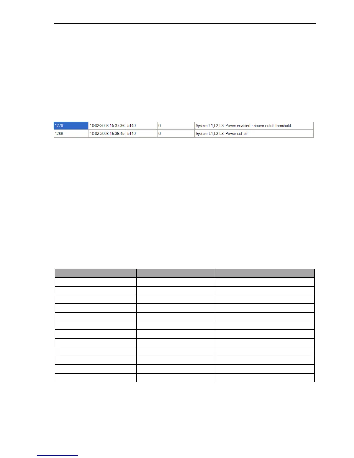
3.5.4 Time stamp with RTC
The time registration is made both at the the apperance of the voltage failure and at the return of voltage. An
example of this registration can be see in Figure 7, showing a read out from METERTOOL.
Figure 7: Logger registration of a voltage failure and re-power with correspondng log IDs and time stamps.
3.6 Loggers
The meter has several different loggers for registration of data and events, among others a debiting logger and
different loggers that secure the registration of events – as to internal errors, magnetic influence, access
registration (Tamper), clock, and voltage failure, load profile logger, andan analysis logger. The load profile and
analysis loggers share the same logging depth, which means that the depth of the analysis logger depends on the
logging depth of the load profile logger and thus the configuration of the meter.
3.6.1 Debiting logger
The debiting logger stores relevant data for a given period. The end of a debiting period is called debiting stop. A
debiting stop can be triggered by the meter’s internal clock or via a communication command.
With its logging depth of 36 loggings, the debiting logger makes it possible to store data for many purposes, e.g.
as a monthly logger controlled by either an internal RTC or an external unit. In the standard version, the loggings
are initiated by the meter’s time. The time for debiting stop has many options, e.g. monthly, every other month,
every six months or yearly.
The debiting logger stores the following values at debiting stop depending on the meter’s configuration:
Various Energy registers Power registers
Date Active energy A+