TECHNICAL DESCRIPTION Kamstrup 162M/382M
5512-1040 GB/05.2012/Rev. C1
43
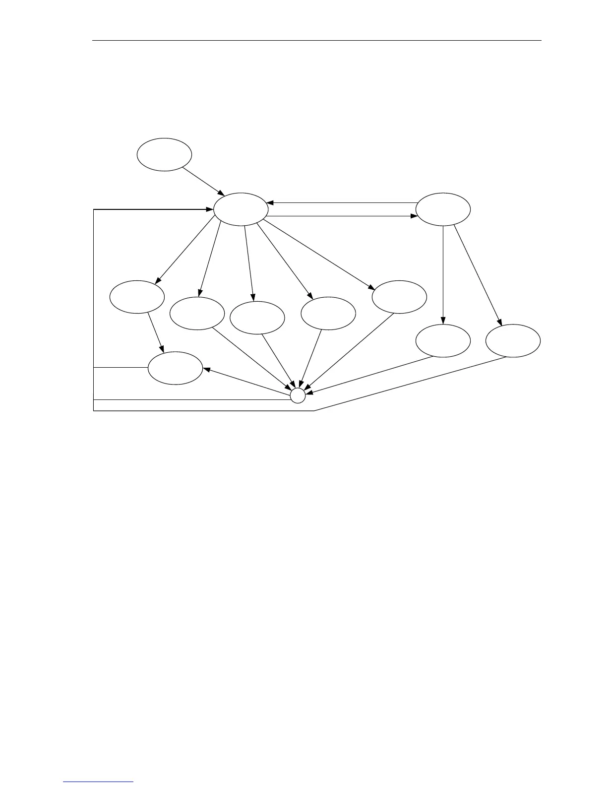
6.6 Status chart of the disconnect function
Figure 18 shows the state-diagram for the disconnect functionality.
State 0
Relays – IN
LED – OFF
State 5
Relays – IN
LED – OFF
State 3 (4)
Relays – IN
LED – OFF
State 9
Relays – OUT
LED – RED
State 1
Relays – OUT
LED – RED
State 12
Relays – OUT
LED – RED
State 6
Relays – OUT
LED – RED
State 7
Relays – OUT
LED – RED
State 11
Relays – OUT
LED – RED
State 2 (8)
Relays – OUT
LED – GREEN
State 13
Relays – IN
LED – OFF
P/I > I
disconnect
P/I < I
disconnect
Pre Cut-off warningNormal opration
Disconnected
Push button
Disconnected
Prepayment
Disconnected
T
prepayment
Disconnected
Commando
Disconnected
Neutral fault
Disconnected
Current/Power
Only log
Automatic reconnect
- Push button
- Command
Manual
reconnect
Ready to reconnect
Figure 18: State diagram of disconnect functionality.