6-4
KaVo OP 3D Vision Service Manual
032-0358-EN Rev B
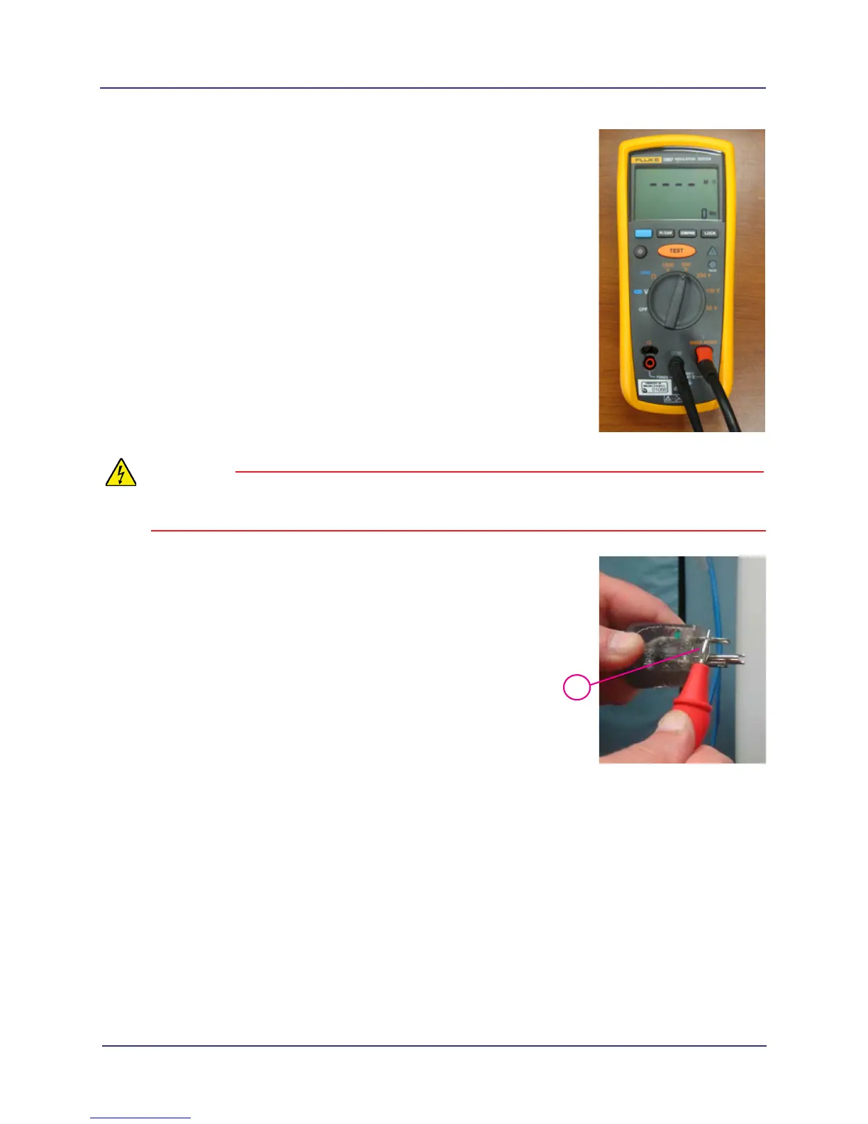
3. Set up Fluke 1507 meter:
a. Insert connector for red probe in V INSULATION receptacle
on meter.
b. Insert connector for black clamp in COM receptacle.
c. Set switch to 500 V.
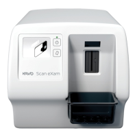
4. At scanner, place black clamp on grounded metal part.
WARNING
The next step will apply 500 VDC to probe. Do not touch probe while test button on probe is
engaged.
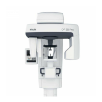
5. Place red probe across the line and neutral prongs of scanner
power cord and push test button on probe.
6. Check reading on meter. Acceptable reading is a value
greater than 2 Megaohms.
7. Remove meter and replace receptor cover.
8. Plug scanner power cord into wall outlet and replace bracket
(if removed).
5






 To Next Page