6-3
Safety Checks
032-0358-EN Rev B
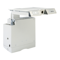
3. Set up Fluke 1507 meter and zero out meter:
a. Insert connector for red probe in receptacle on meter.
b. Insert connector for black clamp in COM receptacle.
c. Set switch to (ZERO) position.
d. Place black clamp on red probe to short probes.
e. Press and hold blue button until ZERO is displayed on meter.
4. At scanner, place black clamp on grounded metal part.
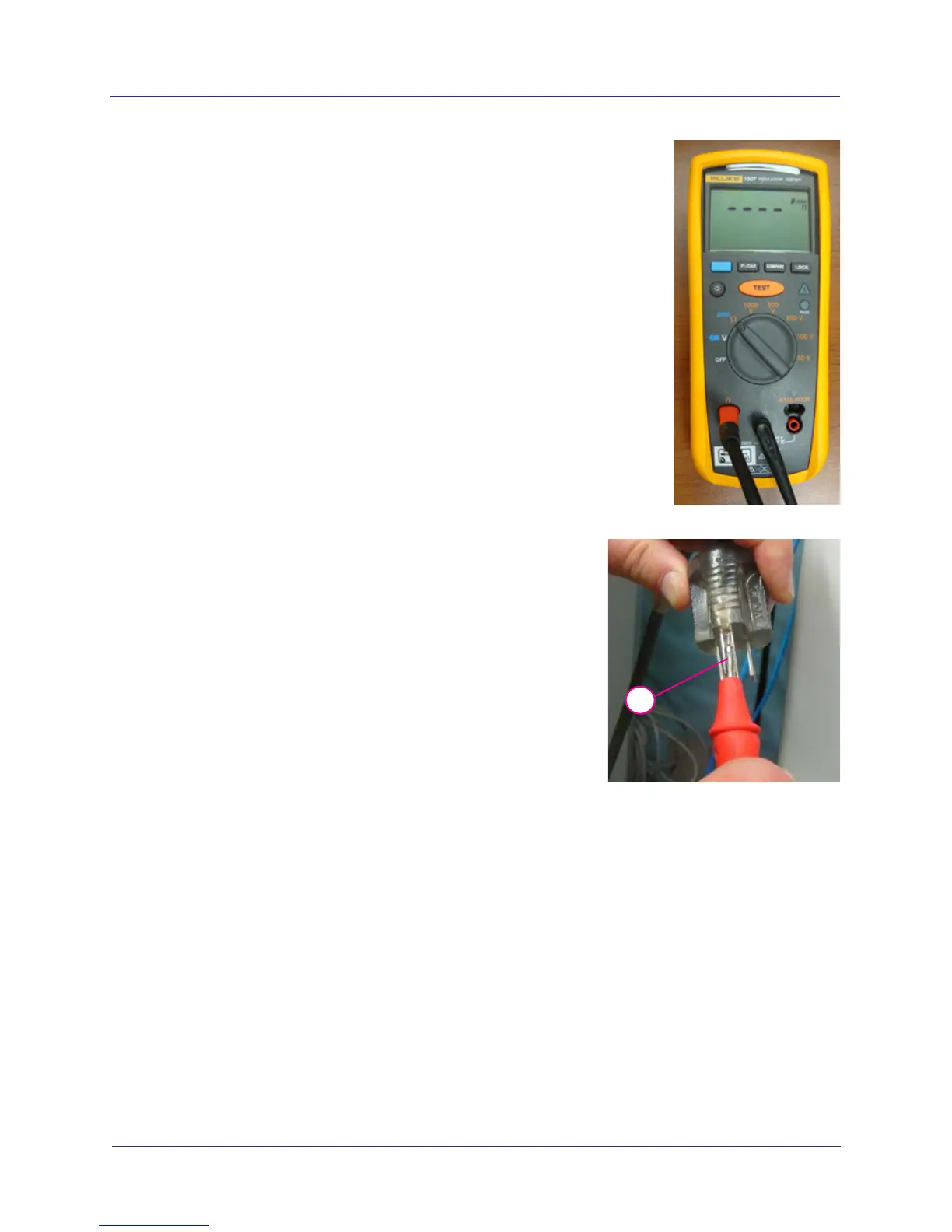
5. Place red probe on safety ground prong of scanner power
cord and push test button on probe.
6. Check reading on meter. Acceptable reading is a value less
than 3 ohms.
7. Leave meter in place, receptor cover off and scanner
unplugged for Insulation Resistance test.
Insulation Resistance
Purpose: Measures the insulation resistance between the line and neutral prongs of the scanner power
cord and grounded metal parts on the scanner.
Test Equipment: Fluke 1507 - Insulation Tester
Acceptable Value: Greater than 2 Megaohms.
1. Perform steps 1 - 2 in Protective Earth Resistance procedure if not already done.
2. Set scanner power circuit breaker at rear of scanner to on position.
5

 Loading...