GB - 84
Connection Power Unit R6-S
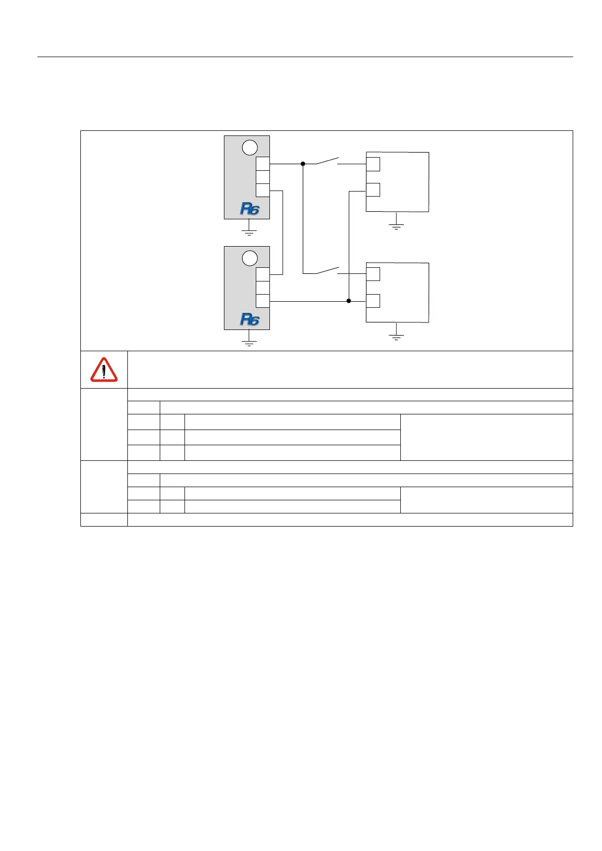
Wiring of the control release of the connected inverter
16
20
G4
25
24
26
S4
G2
X2A
25
24
26
S3
G1
X2A
G3
16
20
AloaddrawintheDC circuit may bedoneonlywhenthemessage„ready“is set.Thiscanbe
guaranteed by a series connection of the relay R1 of the R6-S units with the control release of the
connected inverters.
G1, G2 Regenerative unit COMBIVERT R6-S
X2A Control terminal strip
24
Relay 1 / NO contact
Ready for operation relay
25
Relay 1 / NC contact
26
Relay 1 / switching contact
G3, G4 Frequency inverter COMBIVERT
X2A Control terminal strip
16 Control release This terminal assignment refers only
to one COMBIVERT
20 24 V output
S3, S4 Control release for COMBIVERT
 Loading...

