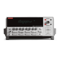
4 Display annunciators
5 Input connector
6 Handle
Pull out and rotate to desired position.
* (asterisk) Readings being stored in buffer.
↔ (more) Indicates additional selections are available.
))
)
(speaker) Beeper on for limit testing.
AUTO Autorange enabled.
BUFFER Recalling readings stored in buffer.
CH1 Channel 1 input displayed.
CH2 Channel 2 input displayed.
CH1 and CH2 Ratio (V1/V2) reading displayed.
ERR Questionable reading, or invalid cal step.
FAST Fast (0.1 PLC) reading rate selected.
FILT Filter enabled.
HOLD Instrument in hold mode.
LSTN Instrument addressed to listen over GPIB.
MATH mX+b or Percent (%) calculation enabled.
MED Medium (1 PLC) reading rate selected.
REAR Indicates that Analog Output is on.
REL Relative enabled for present measurement function.
REM Instrument in GPIB remote mode.
SCAN Scan mode selected.
SHIFT Accessing a shifted key.
SLOW Slow (5 PLC) reading rate selected.
SRQ Service request over GPIB.
STAT Displaying buffer statistics.
STEP Step mode selected.
TALK Instrument addressed to talk over GPIB bus.
TIMER Timer controlled scans in use.
TRIG External triggering (front panel, bus or trigger link) selected.
CHANNEL 1 Measure voltage or temperature. Volts Ranges: 10mV, 100mV, 1V,
10V, and 100V.
CHANNEL 2 Measure voltage or temperature. Volts Ranges: 100mV, 1V, and 10V.
1-10
Getting Started

 Loading...