DISPlay, FORMat, and SYSTem 10-5
ASCII # sign and 0. Not shown in Figure 10-1 is a byte for the terminator that is attached to the
end of each data string.
DREal selects the binary IEEE-754 double precision data format and is shown in Figure 10-2
(normal byte order shown). This format is similar to the single precision format except that it is
64 bits long.
During binary transfers, never un-talk the power supply until after the data is read (input) to
the computer. Also, to avoid erratic operation, the readings of the data string (and terminator)
should be acquired in one piece. The header (#0) can be read separately before the rest of the
string.
The number of bytes to be transferred can be calculated as follows:
Bytes = 2 + (Rdgs × 4) + 1 for SREAL
Bytes = 2 + (Rdgs × 8) + 1 for DREAL
where: 2 is the number of bytes for the header (#0).
Rdgs is the number of readings to be transferred.
4 or 8 is the number of bytes for each reading.
1 is the byte for the terminator.
For example, assume that the power supply is configured to trigger 10 voltage readings and
send the 10 voltage measurements to the computer using the binary format.
Bytes = 2 + (10 × 4) + 1 = 43 for SREAL
Bytes = 2 + (10 × 8) + 1 = 83 for DREAL
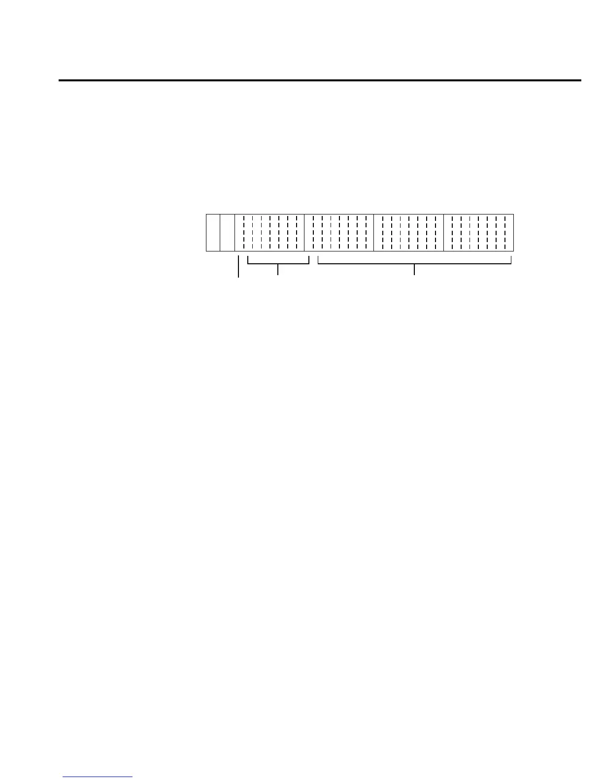
Byte 1
70
Header
# 0
Byte 2
70
Byte 3
70
Byte 4
70
se f
s = sign bit (0 = positive, 1 = negative)
e = exponent bits (8)
f = fraction bits (23)
Normal byte order shown. For swapped byte order,
bytes sent in reverse order: Header, Byte 4, Byte 3,
Byte 2, Byte 1.
The Header is only sent once for each measurement conversion.
Figure 10-1
IEEE-754 single precision data format

 Loading...


