6-2 GPIB Operation
Introduction
The GPIB bus is the IEEE-488 instrumentation data bus with hardware and programming
standards originally adopted by the IEEE (Institute of Electrical and Electronic Engineers) in
1975. The power supply conforms to these standards:
• IEEE-488-1987.1
• IEEE-488-1987.2
These standards define a syntax for sending data to and from instruments, how the instrument
interprets this data, what registers should exist to record the state of the instrument, and a group
of common commands.
• SCPI 1995.0 (Standard Commands for Programmable Instruments)
This standard defines a command language protocol. It goes one step further than IEEE-488-
1987.2 and defines a standard set of commands to control every programmable aspect of the
instrument.
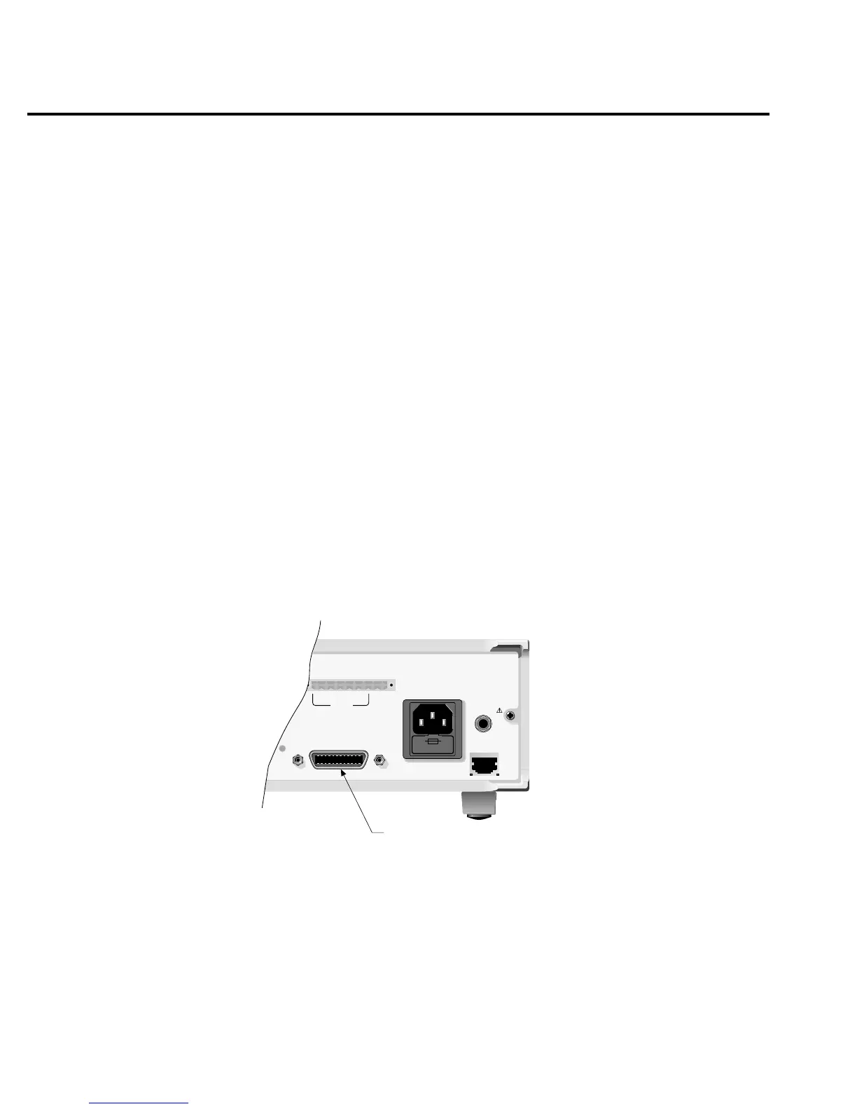
GPIB bus connections
To connect the power supply to the GPIB bus, use a cable equipped with standard IEEE-488
connectors. The IEEE connector on the power supply is shown in Figure 6-1.
NOTE To minimize interference caused by electromagnetic radiation, use only shielded IEEE-
488 cables. Available shielded cables from Keithley are Models 7007-1 and 7007-2.
For a multi-unit test system, you can daisy-chain the instruments to the controller by connect-
ing an IEEE cable from one unit to another.
Most controllers are equipped with an IEEE-488 style connector, but a few may require a dif-
ferent type of connecting cable. See the controller’s instruction manual if it is not equipped with
an IEEE-488 style connector.
WARNING:NO INTERNAL OPERATOR SERVICABLE PARTS,SERVICE BY QUALIFIED PERSONNEL ONLY.
WARNING:NO INTERNAL OPERATOR SERVICABLE PARTS,SERVICE BY QUALIFIED PERSONNEL ONLY.
CAUTION:FOR CONTINUED PROTECTION AGAINST FIRE HAZARD,REPLACE FUSE WITH SAME TYPE AND RATING.
CAUTION:FOR CONTINUED PROTECTION AGAINST FIRE HAZARD,REPLACE FUSE WITH SAME TYPE AND RATING.
MADE IN
U.S.A.
LINE RATING
100-120VAC/
200-240VAC
50, 60 HZ
150VA MAX
LINE FUSE
SLOWBLOW
2.0A, 250V
IEEE-488
(CHANGE IEEE ADDRESS
WITH FRONT PANEL MENU)
REMOTE
DISPLAY
OPTION
ISOLATION FROM EARTH:
22 VOLTS MAX.
+++
____
+
SOURCE SENSE
DVM IN
SOURCE
OUTPUT
15V/3A 9V/5A
IEEE-488 Connector
RELAY
CONTROL
15VDC MAX
Figure 6-1
IEEE-488 connector

 Loading...


