2-2 Basic Power Supply Operation
Test connections
WARNING When installing a unit into a test system, make sure the external power
sources do not apply voltage to the power supply in excess of its maximum
limits (see specifications). Failure to do so could result in personal injury or
death.
Test connections to the power supply are made at the rear panel using a quick disconnect
OUTPUT/DVM IN connector (Keithley part number CS-846). Figure 1-1B shows where the
connector plugs in. Use up to #14 AWG wire for the screw terminals of the connector. Once the
connector is wired up, plug it into the rear panel and tighten the captive retaining screws.
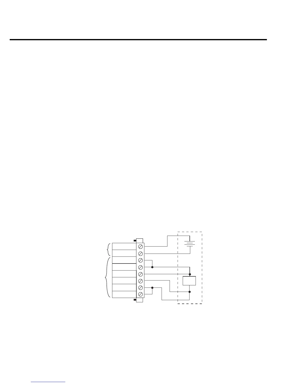
Figure 2-1 shows typical power supply connections to the device under test.
NOTE Source I/O terminals are rated up to 10A maximum per pin. Two sets of Source +
and Source - terminals are available. This configuration allows you to wire source
connections in parallel to reduce the effects of wire impedance or to have two sep-
arate loads. The two Source + pins and the two Source - pins are internally con-
nected to respective terminals on the PC board.
Quick
Disconnect
Connector
(Part # CS-846)
DVM
Input
Output
External
Test
Circuitry
DUT
Sense +
Sense -
Source +
Source -
DVM -
DVM +
Source -
Source +
+
_
Figure 2-1
Typical connections

 Loading...


