Status Structure 7-3
3
5
6
Cal
9
10
11
12
13
14
15
Condition
Register
(Always Zero)
3
5
6
9
10
11
12
13
15
Event
Register
3
5
6
9
10
11
12
13
15
Event
Enable
Register
&
&
&
&
&
&
&
&
&
&
&
&
&
&
&
&
Logical
OR
7
8
11
12
13
15
Condition
Register
Event
Register
Event
Enable
Register
&
&
&
&
&
&
&
&
&
&
&
&
&
&
&
&
Logical
OR
EAV
QSB
MAV
ESB
RQS/MSS
OSB
Status
Byte
Register
1
EAV
QSB
MAV
ESB
6
OSB
Service
Request
Enable
Register
&
&
&
&
&
&
&
Logical
OR
*STB?
*SRE
*SRE?
Master Summary Status (MSS)
MSB = Measurement Summary Bit
EAV = Error Available
QSB = Questionable Summary Bit
MAV = Message Available
ESB = Event Summary Bit
RQS/MSS = Request for Service/Master Summary Staus
OSB = Operation Summary Bit
Error Queue
Output Queue
Note : RQS bit is in serial poll byte,
MSS bit is in *STB? response.
1
14 14
OPC
QYE
DDE
EXE
CME
URQ
PON
8
9
11
12
13
15
Register
8
9
11
12
13
15
Register
&
&
&
&
&
&
&
&
&
&
&
&
&
&
&
&
Logical
OR
(Always Zero)
Operation Complete
Query Error
Device Specific Error
Execution Error
Command Error
User Request
Power On
OPC
QYE
DDE
EXE
CME
URQ
PON
*ESR?
*ESE?
MSB MSB
12
13
14
15
(Always Zero)
Event
Register
Event
Enable
Register
&
&
&
&
&
&
&
&
&
&
&
&
&
&
&
&
Logical
OR
Condition
Register
RAV
Reading Available
11
Calibration Summary
2
10
9
1
11
4
4
4
0
1
2
0
1
2
0
1
2
6
Buffer Full
7
14
:CONDition? [:EVENt]? :ENABle <NRf>
:ENABle?
Questionable Event Registers
14
14
10
10
*ESE <NRf>
Event
Event Enable
Standard Event Registers
8
BF
7
Pulse Trigger Timeout PTT
Reading Overflow
ROF
2
1
0
:CONDition?
[:EVENt]?
:ENABle <NRf>
:ENABle?
CL
CLT
5
PSS
10
Current Limit Tripped
Power Supply Shutdown
(Always Zero)
0
Current Limit
:CONDition? [:EVENt]?
:ENABle <NRf>
:ENABle?
Operation Event Registers
Cal
7
Cal
7
Measurement Event Registers
12
13
14
15
RAV
10
11
6
8
BF
7
PTT
ROF
2
1
0
12
13
14
15
RAV
10
11
6
8
BF
7
PTT
ROF
2
1
0
14
7
8
11
12
13
15
2
9
1
CL
CLT
5
PSS
10
0
14
7
8
11
12
13
15
2
9
1
CL
CLT
5
PSS
10
0
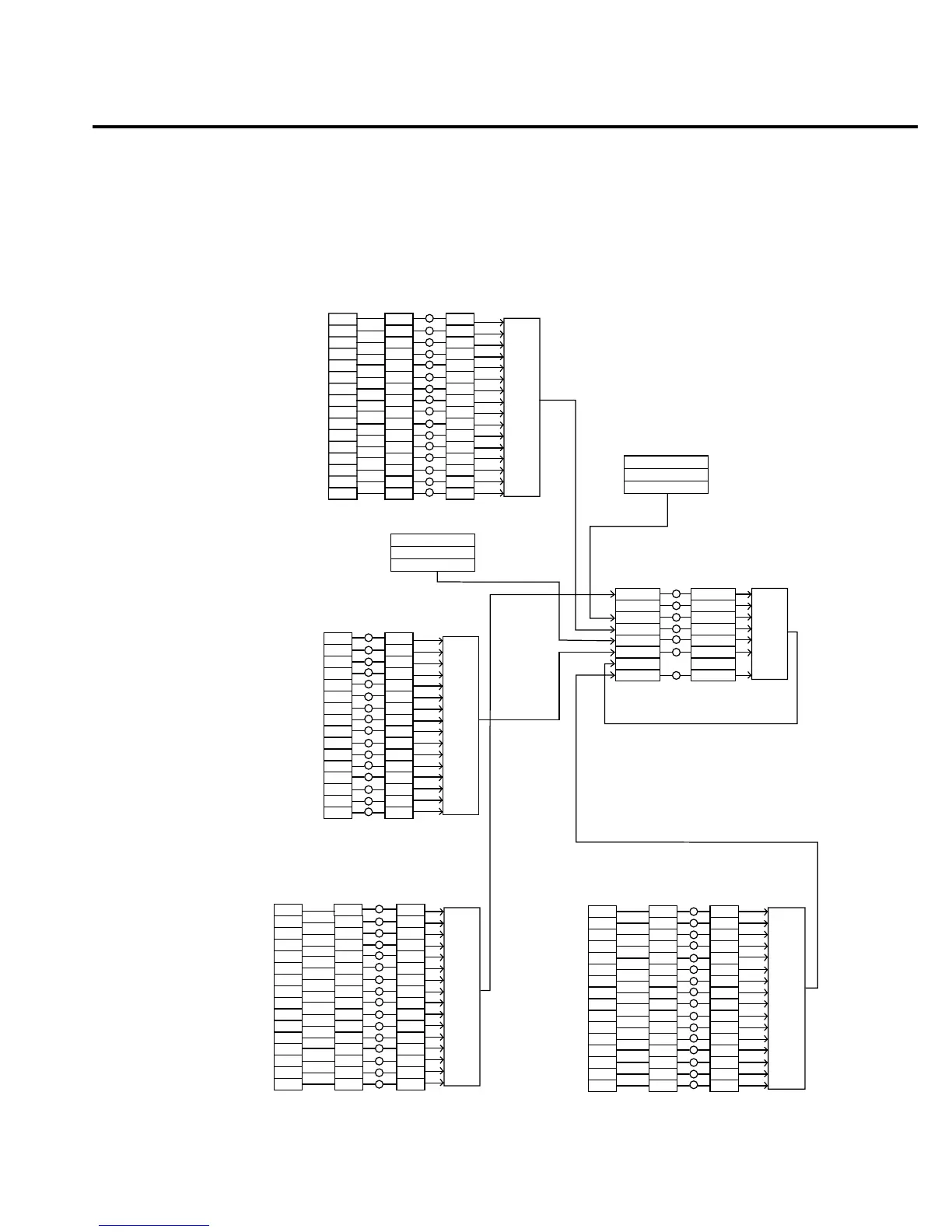
Figure 7-1
Status model structure

 Loading...


