5-44 Delta, Pulse Delta, and Differential Conductance Model 6220/6221 Reference Manual
Return to Section 5 topics
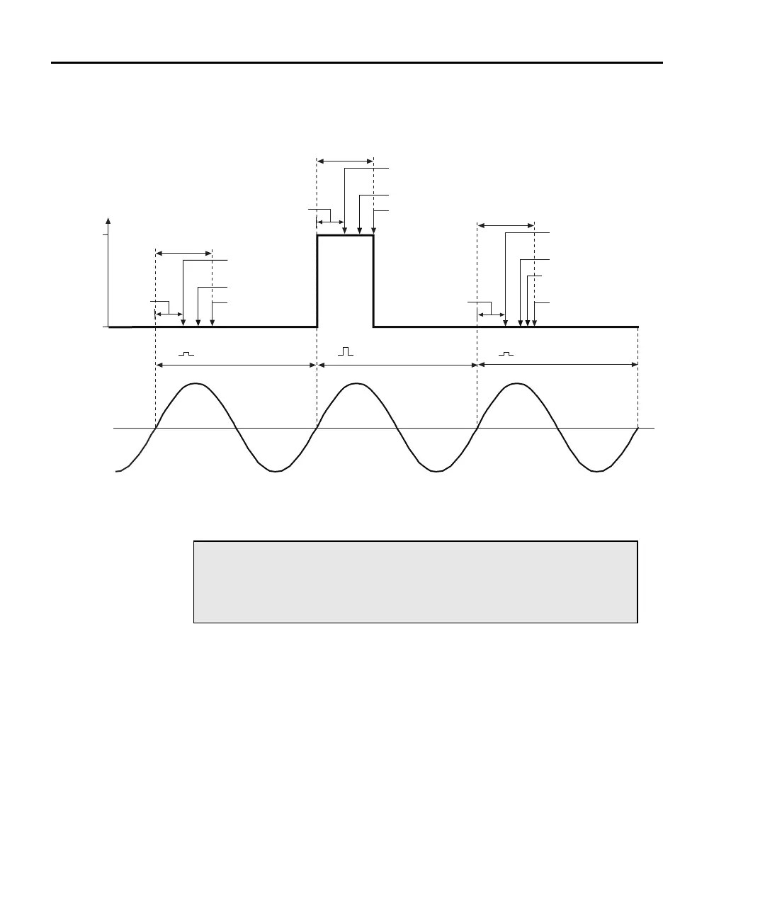
Figure 5-12
Pulse Delta triggering sequence (two lows measured)
Operation
Pulse Delta operation – front panel
The system configuration for front panel stand-alone operation is shown in Figure
5-2A on page 5-5.
1. Connections are shown in the following illustrations. All power must be
removed from all components in the system before making connections:
• Figure 5-3, page 5-7 – System connections
• Figure 5-5, page 5-10 – DUT test connections
2. Configure communications for the Models 2182A and 6221 as explained in
“Configuring communications,” on page 5-10.
3. On the Model 2182A, select the desired measurement range (using the
RANGE keys).
NOTE Pulse Delta readings from the Model 2182A will
be unfiltered. Noisy readings can be filtered by
the Model 622x before sending them into the
buffer. See Section 6 for details.
I-High
I-Low
Power
Line
Voltage
Pulse Width
6221 Output
Trigger
2182A A/D #2
2182A Output
Trigger
Source
Delay
Pulse Width
6221 Output
Trigger
2182A A/D #1
2182A Output
Trigger
Source
Delay
Pulse Width
6221 Output
Trigger
2182A A/D #3
2182A Output
Trigger
Source
Delay
Pulse Delta
Reading
One Line Cycle
One Line Cycle
One Line Cycle
6221
Output
Low
High Low
Test Equipment Depot - 800.517.8431 - 99 Washington Street Melrose, MA 02176 - TestEquipmentDepot.com