E8257D/67D, E8663D PSG Signal Generators Service Guide 33
Troubleshooting
Troubleshooting Assembly–Level Problems
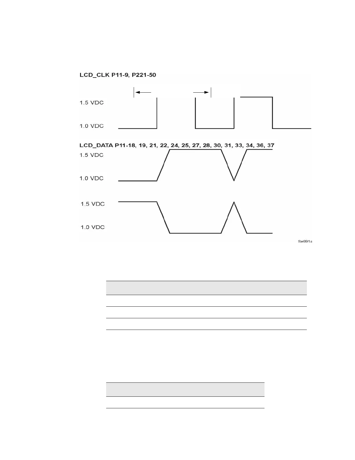
The pulse state signals are control lines, clock, and data for the LCD.
Figure 1-1 Pulsing Activity
5. If all the signals measured in Step 4 are good, go to Step 6.
If any of the signals measured in Step 4 are bad, check the following
signals at P221 of the motherboard:
If any of these signals are bad, change the CPU board.
6. If all the signals measured in Step 4 are good, check the following signals
at J9 of the power switch. To access J9 the front panel must be removed
from the chassis frame and laid face down.
Signal State
P221−14 VLCD approximately 21 Vdc
P221−53 LCD_ENABLE_H >3 Vdc
P221–1 to 13, 15, 41, 43, 45, 47, 49 to 52 Refer to Figure 1-1 on page 33.
Signal State
J9−7 VLCD approximately 21 Vdc