406 E8257D/67D, E8663D PSG Signal Generators Service Guide
Post–Repair Procedures
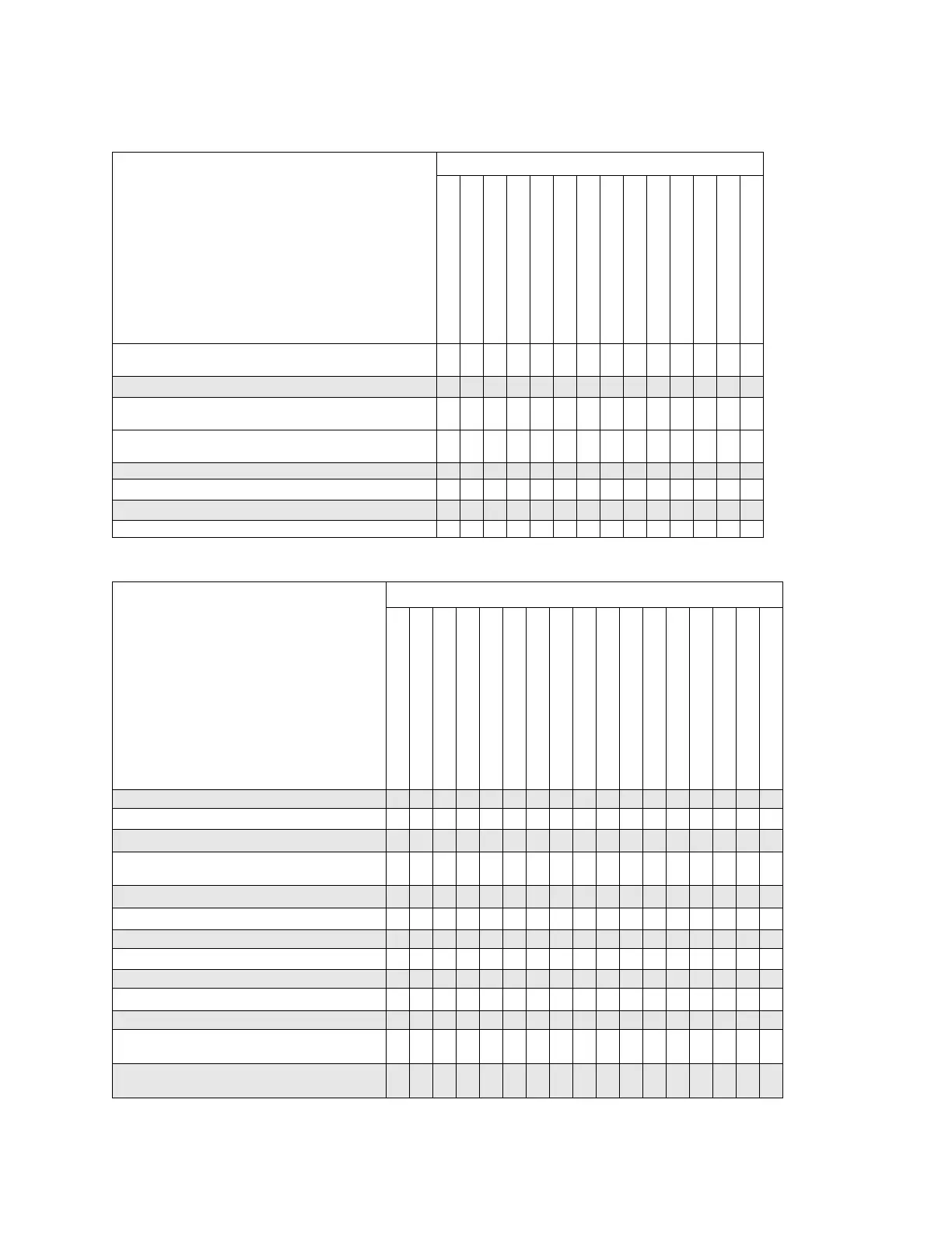
Post–Repair Procedures Matrix
V-Band Low Power Attenuator Accuracy (E8257D with Option 567
and 1E1 Only)
X
V-Band ALC Modulator Calibration (E8257D with Option 567 Only)
X
Ramp Sweep Calibration (E8257D/E8663D with 007 and E8257N
Only)
X
X
Pulse Width calibration (E8257D with Option UNU, UNW, UNS, or
HNS, and E8663D/E8257N Only)
X
Low Band Digital Prelevel Calibration X
VBLO Mixer Bias Calibration X
Low Band Digital Gain Calibration X
9V PTAT ABUS Measure Calibration X
Table 4-5 Post-Repair Adjustments: Assemblies A13—A26 (For prefixes >= xx4928)
Adjustments Replaced Assembly
The following adjustments are listed in the order that
they should be performed for proper calibration.
A13 IQ Mul tiplexer
A14 Baseband Generator
A17 Baseband Generator Interface
A18 CPU
A19 Power Supply
A20 SMI [Source Module Interface]
A21 Rear Panel
A22 Line Module
A23 Lowband Coupler/Detector
A24 20 GHz Coupler
A24 40 GHz Coupler
A24 67 GHz Coupler
A25 20 GHz Detector
A25 40 GHz Detector
A25 67 GHz Detector
A25B Detector Bias Board
A26 MID
ADC Calibration X X
High Band ALC Linearity Calibration
X X X X
High Band Power Flatness Calibration
X X X X
High Band High Power ALC linearity Calibration (E8257D
with Option 521 Only)
X X X X
Low Band ALC Linearity Calibration
X X X X
Low Band ALC Linearity Calibration
X
Low Band Power Flatness Calibration X
Low Band High Power ALC Linearity Calibration
X
User Clamp Calibration (Option 1EU Only) X
Low Band Power Maximum Calibration
X
Low Band ALC Modulator Prep Calibration X
V-Band Power Flatness Calibration (E8257D with Option
567 Only)
X X
V-Band Low Power Attenuator Accuracy (E8257D with
Option 567 and 1E1 Only)
Table 4-4 Post-Repair Adjustments: Assemblies A1—A11 (For prefixes >= xx4928)
Adjustments Replaced Assembly
The following adjustments are listed in the order that they should
be performed for proper calibration.
A1 Keyboard
A2 Display
A2DS1 Display Backlight
A3 Power Switch
A4 Inverter
A5 Sampler
A6 Frac-N
A7 Reference (Standard)
A7 Reference (Option UNR/UNX)
A8 Output (Analog)
A8 Output (Digital)
A9 YIG Driver
A10 ALC
A11 Pulse/Analog Mod Gen