E8257D/67D, E8663D PSG Signal Generators Service Guide 405
Post–Repair Procedures
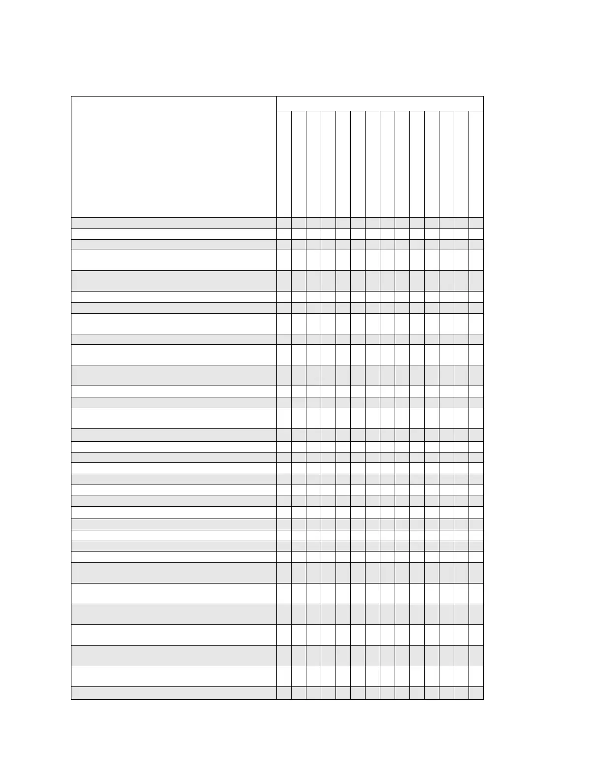
Post–Repair Procedures Matrix
FM Scale Offset Calibration (E8257D/E8663D with Option UNT) X X X
FM Path Offset Calibration (E8257D/E8663D with Option UNT) X X X
FM In-band Offset Calibration (E8257D/E8663D with Option UNT) X X X
FM Inverting Amplifier Offset Calibration (E8257D/E8663D with
Option UNT)
X
FM 1/2 Path Ratio Gain Calibration (E8257D/E8663D with Option
UNT)
X X X
Mod Source Relative Gain Calibration X X X
FM/PM Out–of–Band Calibration X X X
FM/PM YO Frequency Compensation Calibration (E8257D/E8663D
with Option UNT and E8257N Only)
X X X
DC FM Calibration (E8257D/E8663D with Option UNT) X X X
Low Frequency Output Calibration (E8257D/E8663D with Option
UNT)
X
External Input Peak Detector Calibration (E8257D/E8663D with
Option UNT)
X
High Band ALC Linearity Calibration X
High Band Power Flatness Calibration X
High Band High Power ALC linearity Calibration (E8257D with
Option 521 Only)
X
High Band ALC Modulator Calibration
X
AM Gain Calibration (E8257D/E8663D with Option UNT) X X
Low Band ALC Linearity Calibration X X X
Low Band Power Flatness Calibration X X X
Low Band High Power ALC Linearity Calibration X X X
User Clamp Calibration (Option 1EU Only) X
Low Band Bypass Gain Calibration X X X X X
Power Clamp Calibration
X
X
X
Low Band Power Maximum Calibration X X X
Low Band ALC Modulator Prep Calibration X X X
ALC Modulator Offset DAC Sensitivity Calibration X X X
Low Band ALC Modulator Calibration X X X
Low Band Scan Modulator Calibration (E8257D/E8663D with option
HSM or 1SM)
X X
High Band Scan Modulator Calibration (E8257D/E8663D with
option HSM or 1SM)
X
User Clamp Refinement Calibration (E8257D/E8663D with Option
HSM or 1SM and Option 1EU Only)
X
Power Clamp Refinement Calibration (E8257D/E8663D with Option
HSM or 1SM Only)
X
Low Band Power Maximum Refinement Calibration
(E8257D/E8663D with Option HSM or 1SM Only)
X
X
Low Band ALC Modulator Refinement Calibration (E8257D/E8663D
with Option HSM or 1SM Only)
X X
V-Band Power Flatness Calibration (E8257D with Option 567 Only)
X
Table 4-4 Post-Repair Adjustments: Assemblies A1—A11 (For prefixes >= xx4928)
Adjustments Replaced Assembly
The following adjustments are listed in the order that they should
be performed for proper calibration.
A1 Keyboard
A2 Display
A2DS1 Display Backlight
A3 Power Switch
A4 Inverter
A5 Sampler
A6 Frac-N
A7 Reference (Standard)
A7 Reference (Option UNR/UNX)
A8 Output (Analog)
A8 Output (Digital)
A9 YIG Driver
A10 ALC
A11 Pulse/Analog Mod Gen