74 Keysight Infiniium MXR-Series Real-Time Oscilloscopes User's Guide
6 Testing Performance
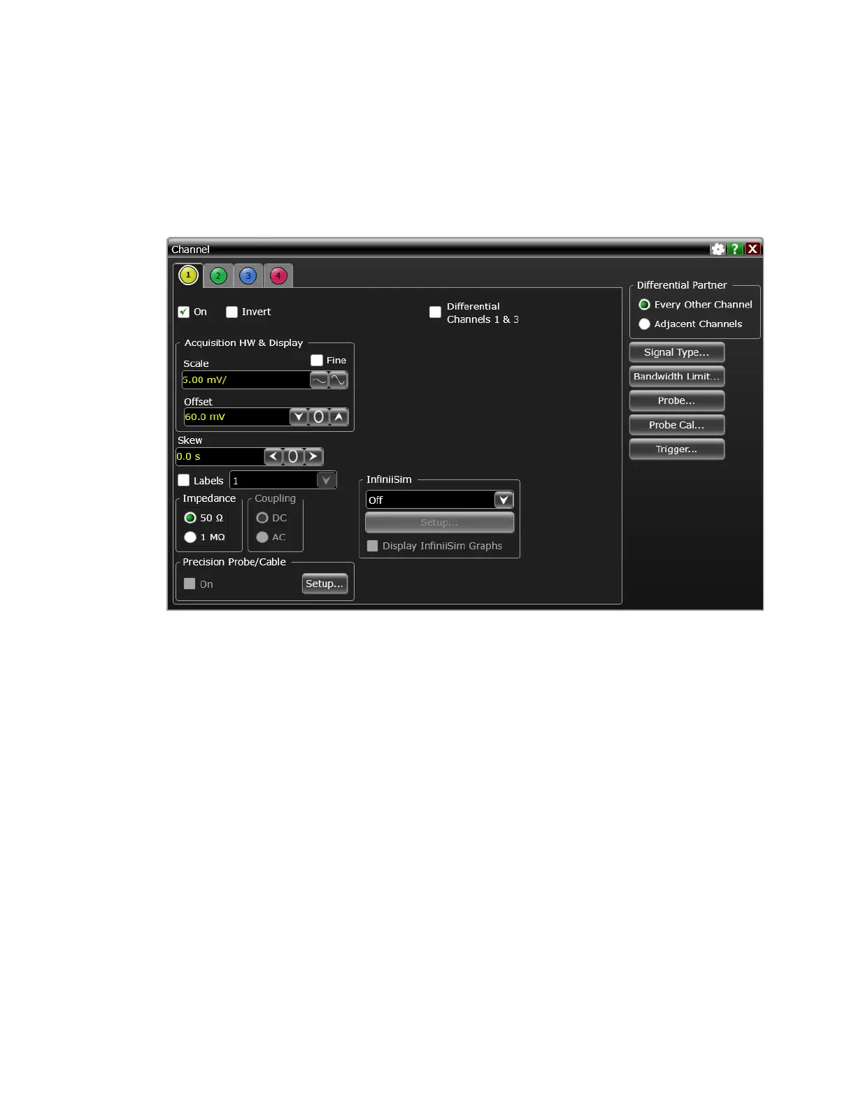
18 Using the Channel dialog box, set the channel's offset value to 60.0 mV and the
impedance to 50 Ω (or to an offset of 2 V and the impedance to 1 MΩ if this is
your second pass through this test and you are using the 1 MΩ input
impedance version).
19 Set the DC supply voltage (External Supply Setting) to +60.0 mV (or +2 V for
the 1 MΩ version of this test).
20 Press [Clear Display] on the oscilloscope, wait for the number of averages to
return to 256, and then record the DMM voltage reading as VDMM+ and the
scope V avg reading as VScope+ in either Table 7 or Table 8 (depending on
which version of the test you are on). Fill in the Verror+ column by using the
following equation:
Verror+ = VDMM+ - Vscope+
Verror+ must be within the limits specified by the corresponding Offset
Accuracy Limit listed in the table.
21 Change the channel 1 offset value to -60.0 mV (or -2 V for the 1 MΩ version of
this test).
22 Set the DC supply voltage to -60.0 mV (or -2 V for the 1 MΩ version of this
test).
23 Press [Clear Display] on the oscilloscope, wait for the number of averages to
return to 256, and then record the DMM voltage reading as VDMM- and the
scope V avg reading as VScope- in either Table 7 or Table 8 (depending on
 Loading...


