Testing Performance 6
Keysight Infiniium MXR-Series Real-Time Oscilloscopes User's Guide 73
11 Repeat step 9b and step 10 for the remaining vertical scale settings for channel
2.
12 Repeat step 8 through step 11 for the remaining channels.
13 Ensure that each Vzero-error is less than the corresponding Vzero-error Limit
entry in the Offset Accuracy Test table.
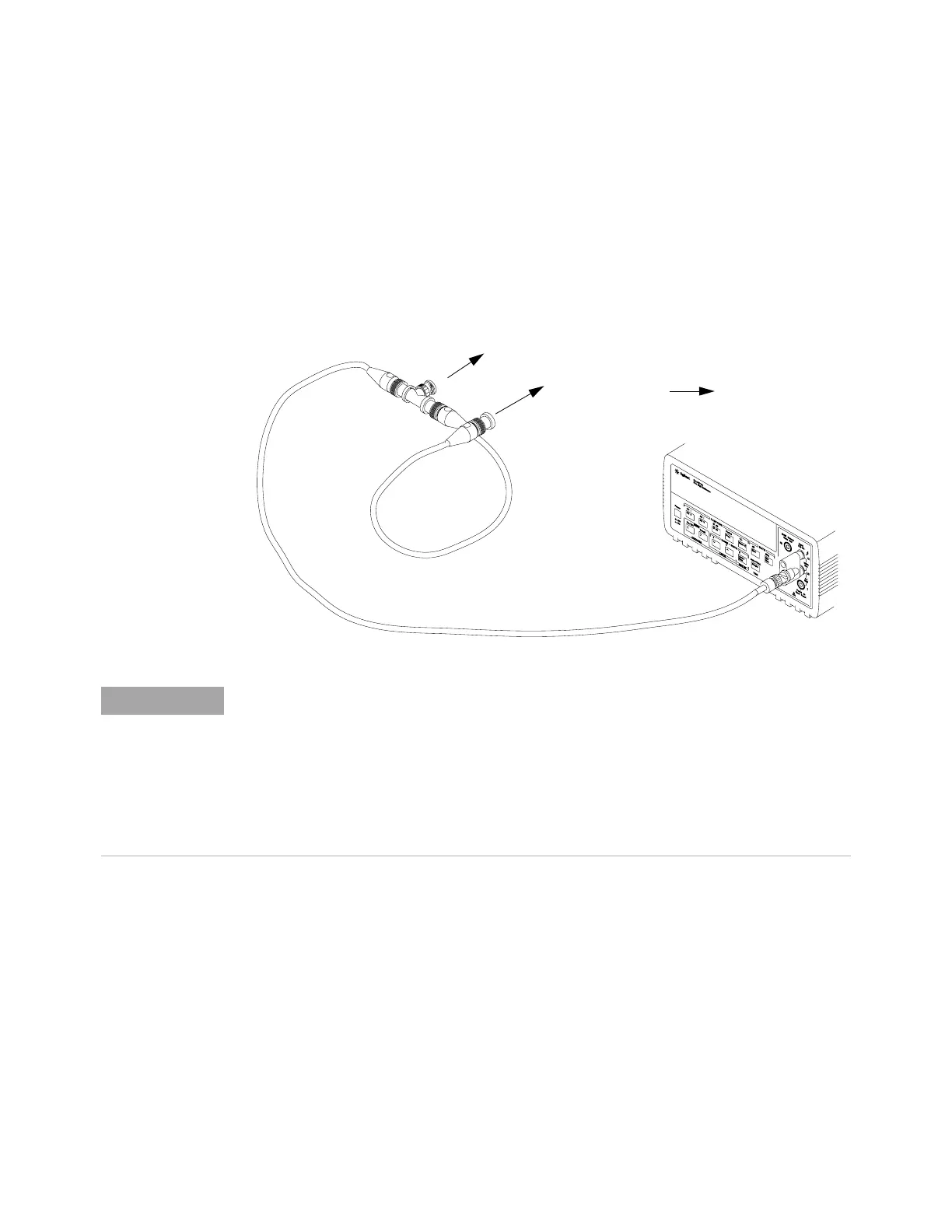
14 Make the connections to oscilloscope channel 1 as shown below.
15 Set up the DMM to perform DC voltage measurements.
16 Click Control > Factory Default to default to channel 1.
17 Configure the oscilloscope to measure the average voltage on channel 1 as
follows:
a Click Setup > Acquisition.... In the Acquisition dialog box, enable averaging
and set # of Averages to 256.
b Change the vertical scale of the channel under test to 5 mV/div.
c Drag and drop the Average voltage measurement icon onto the channel 1
waveform.
Channel Input on MXR-Series Oscilloscope
BNC (f) to dual banana
(1251-2277)
6614C DC Supply
• Where the BNC Tee adapter is used, it is important to connect it directly to the oscilloscope
channel input to minimize ground potential differences and to ensure that the DMM measures the
input voltage to the oscilloscope channel as accurately as possible. Differences in ground
potential can be a significant source of measurement error, particularly at high scope sensitivities.
• It also helps to reduce ground potential differences if the oscilloscope and DMM are connected to
the same AC supply circuit.
• 256 averages are used in the oscilloscope measurements of this section to reduce measurement
noise and to reduce the measurement error due to resolution.
 Loading...


