9
Overview
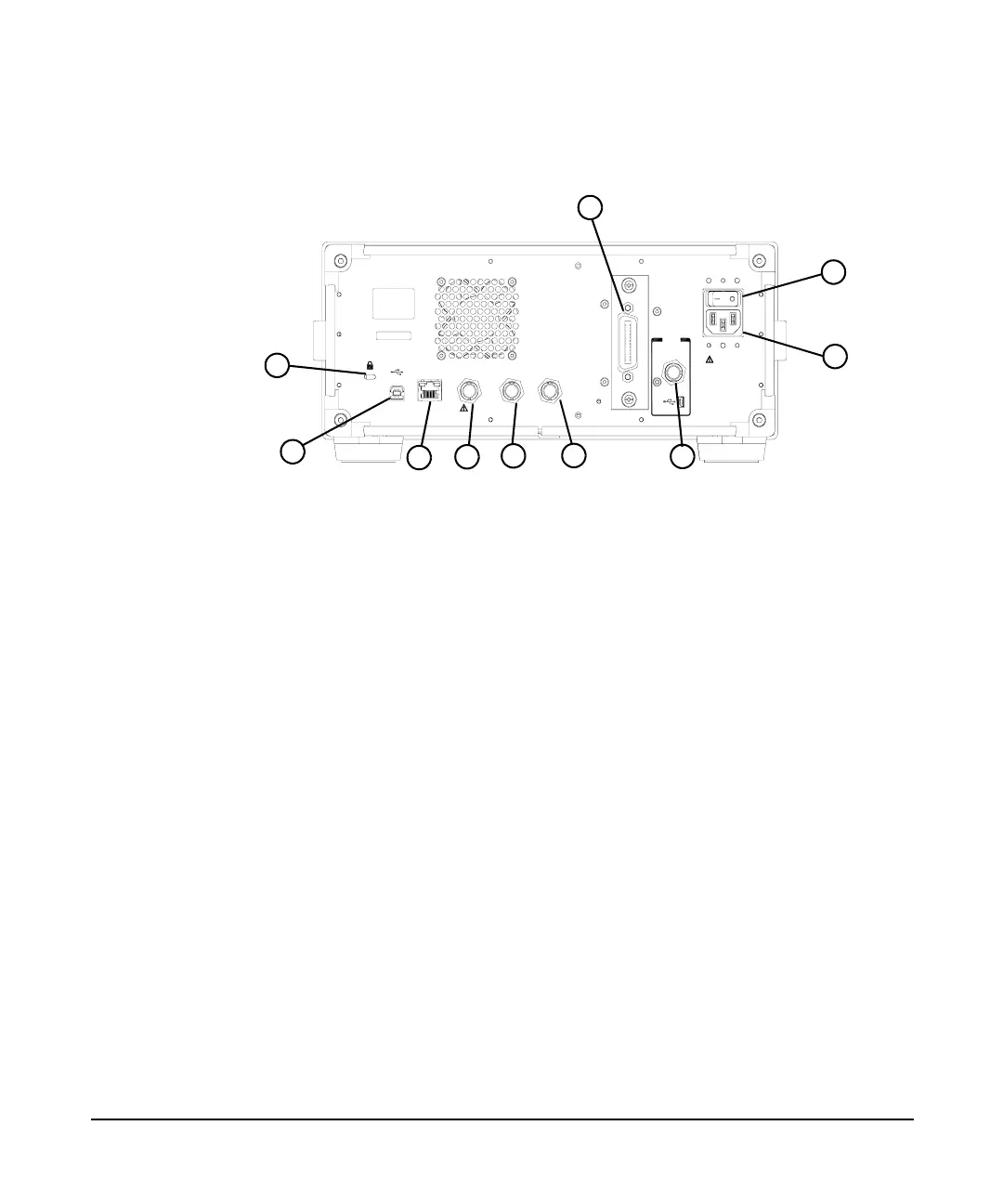
Rear Panel Overview
Rear Panel Overview
1 Kensington Lock lock the instrument and keep its safety.
2 USB Host connector provides a connection between the
analyzer and an PC for remote control.
3LAN port A TCP/IP Interface used for remote operation.
4 EXT TRG IN (TTL) connector accepts an external voltage input,
the positive edge of which triggers the analyzer sweep
function. (BNC female)
5REF IN connector accepts an external timebase with a
frequency of 10 MHz, amplitude of –5 to +10 dBm. (BNC
female)
6 REF OUT connector provides a frequency of 10 MHz, amplitude
of –10 dBm reference output. (BNC female)
7 REF OUT connector (Option PFR) is an optional connector for
precision 10 MHz reference from OCXO.
8AC Power Receptacle accepts a three- pin line power plug.
9Power switch isolates the analyzer from the AC line power.
After switch on, the analyzer enters into standby mode and
the orange standby LED on the front panel lights.
10 GPIB connector (Option G01) is an optional interface. This GPIB
connector supports remote operation.
SERI AL LABEL
ATTACH HERE
HIPOT LABEL
ATT ACH H ERE
LAN
REF OUT
TRIG IN 10MHz
T T L
REF IN
10M Hz
PC
OCXO
REF OUT
10M Hz
~100-240
V
50/ 60
Hz
100
W MAX
1
2
4
7
8
9
10
3
5
6