59
Functions and Measurements
Stimulus Response Transmission
Stimulus Response Transmission
The procedure below describes using the built- in tracking
generator of the analyzer to measure the rejection of a low
pass filter. A type of transmission measurement.
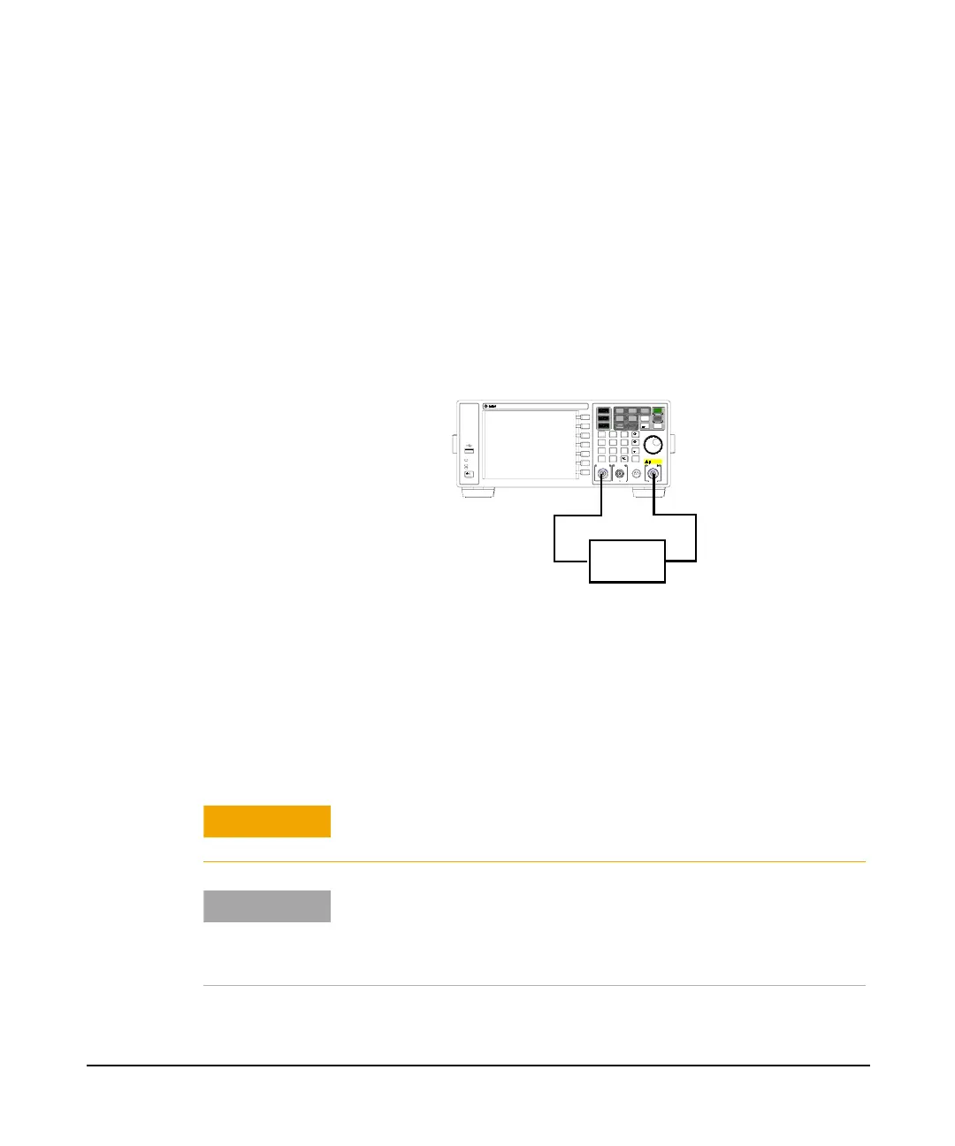
1 To measure the rejection of a low pass filter, connect the
equipment as shown in
Figure 3-18. A 370 MHz low pass
filter as the DUT.
Figure 3-18 Transmission Measurement Test Setup
2 Press Preset. (With Preset Type of Factory)
3 Set the start and stop frequencies and resolution bandwidth:
Press Frequency > Start Freq > 100 > MHz
Press Frequency> Stop Freq > 1 > GHz
Press Bw > 3 > MHz
4 Turn on the tracking generator and if necessary, set the
output power to - 10 dBm:
Press Mode > Tracking Generator > Amplitude (On) > -10 > dBm
Remot e
Standb y
On
TG SOURCE CAL OUT
50MHz 10dBm
7
·
4
1
0
2
5
89
6
3
Back
Enter
Marker
Peak
Search
Marker
Auto
Tune
Det/
Display
File/
Print
BW/
Avg
View/
Trace
MeasMODE
Sweep /
Trig
Local
Save
N9320A SPECTRUM ANALYZER 9 kHz - 3.0 GHz
PROBE POWER
RF IN 50
50VDC MAX
30dBm 1W MAX
CAT Ⅱ
DUT
CAUTION
Excessive signal input may damage the DUT. Do not exceed the
maximum power that the device under test can tolerate.
NOTE
To reduce ripples caused by source return loss, use 6 dB or greater
output attenuation. Tracking generator output attenuation is normally
a function of the source power selected. However, the output
attenuation may be controlled in the Tracking Generator menu.