30 Keysight N9938-90003 User’s Guide
Preparing for Initial Use of Your New FieldFox
Take the FieldFox Tour
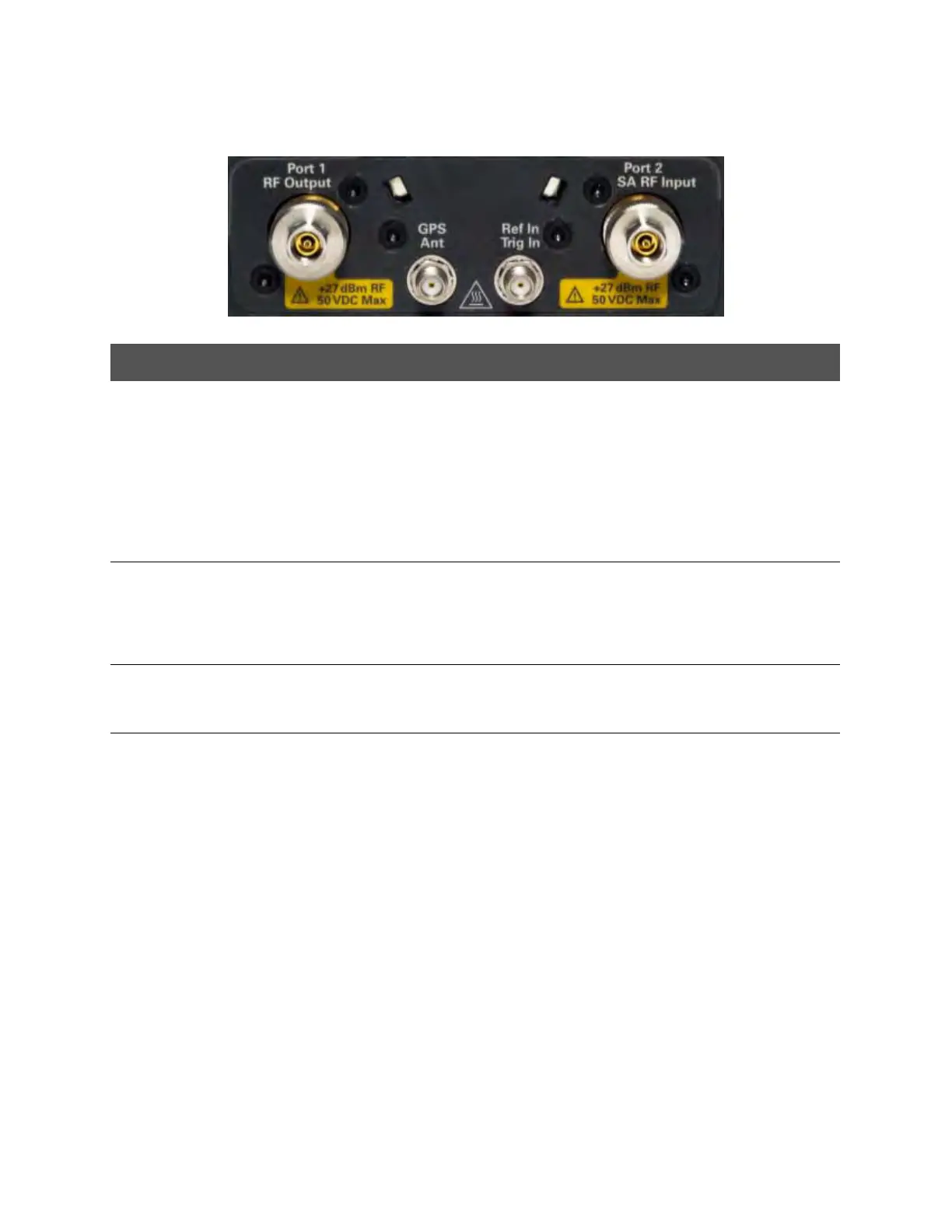
Top Panel
Caption Descriptions Learn More:
Port 1
RF Output
For CAT and NA measurements, use to make reflection measurements.
Maximum: ±50 VDC, +27 dBm RF
Also, for SA source output in SA mode.
“CAT Mode Settings”
on page 39
“NA Mode Settings” on
page 65
Chapter 7, “SA
(Spectrum Analyzer)
Mode (Option
233–Mixed Analyzers)”,
on page 107
Port 2
SA RF Input
For SA, use to make all measurements.
For CAT, NA, and VVM mode, use to make Port 2 transmission
measurements.
Maximum: ±50 VDC, +27 dBm RF.
“SA Mode Settings” on
page 110
GPS Ant SMA (f) connector for use with built-in GPS. Produces a settable 3.3 VDC or
5 VDC bias voltage for the antenna pre-amplifier. Use with a GPS antenna
such as N9910X-825. Other GPS antennas can also be used.
“GPS” on page 236
Ref In
Trig In
SMA (f) connector for use with Frequency Reference Source and External
Trigger Input signal.
Maximum: 5.5 VDC.
“Frequency Reference
Source” on page 250.
“Triggering” on
page 136