Chapter 1: Installation and wiring
P/N 3102351-EN • REV 005 • ISS 28DEC18 29
• All alarm points or zones (if programmed as a zoned system) must be programmed to
activate the dedicated NAC
• The NAC used must be programmed as City Tie
Wiring
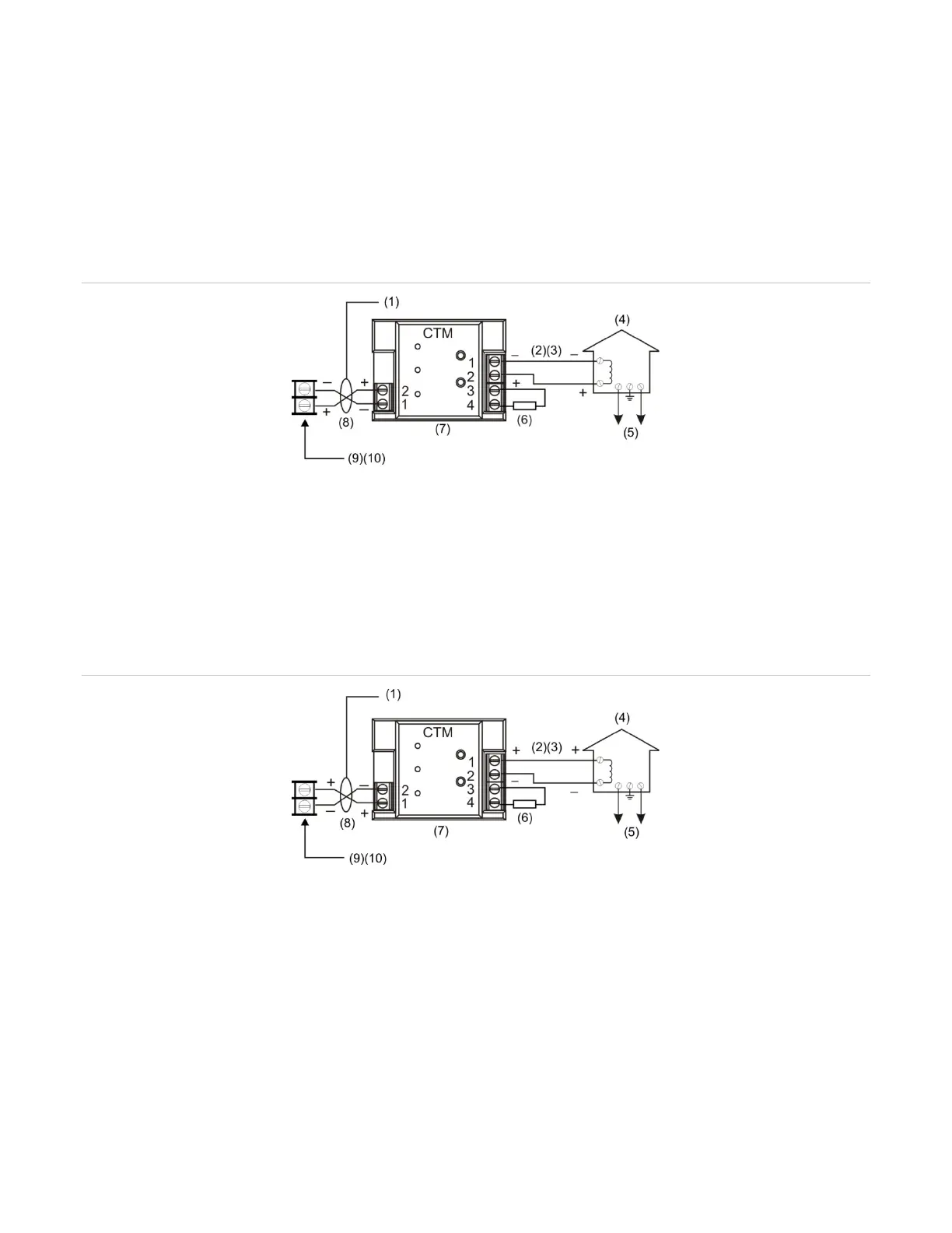
The following wiring diagrams show how the polarity switches during an alarm condition.
Figure 39: CTM module wiring (panel in normal condition)
2) 200 mA into a 14.5 Ω trip coil max. loop
resistance = 25 Ω
This circuit is nonpower-limited and is supervised
for grounds and opens, but not shorts
Master box
(5) Public fire alarm reporting system
(6) 15 kΩ end-of-line resistor
(7) CTM must be mounted in the same room
as the panel
(8) Supervised and power-limited
(9) Notification appliance circuit (NAC)
(10) NAC must be programmed for city tie
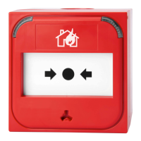
Figure 40: CTM module wiring (panel in alarm condition)
2) 200 mA into a 14.5 Ω trip coil max. loop
resistance = 25 Ω
This circuit is nonpower-limited and is supervised
for grounds and opens, but not shorts
Master box
(5) Public fire alarm reporting system
(6) 15 kΩ end-of-line resistor
(7) CTM must be mounted in the same room
as the panel
(8) Supervised and power-limited
(9) Notification appliance circuit (NAC)
(10) NAC must be programmed for city tie