Chapter 1: Installation and wiring
8 P/N 3102351-EN • REV 005 • ISS 28DEC18
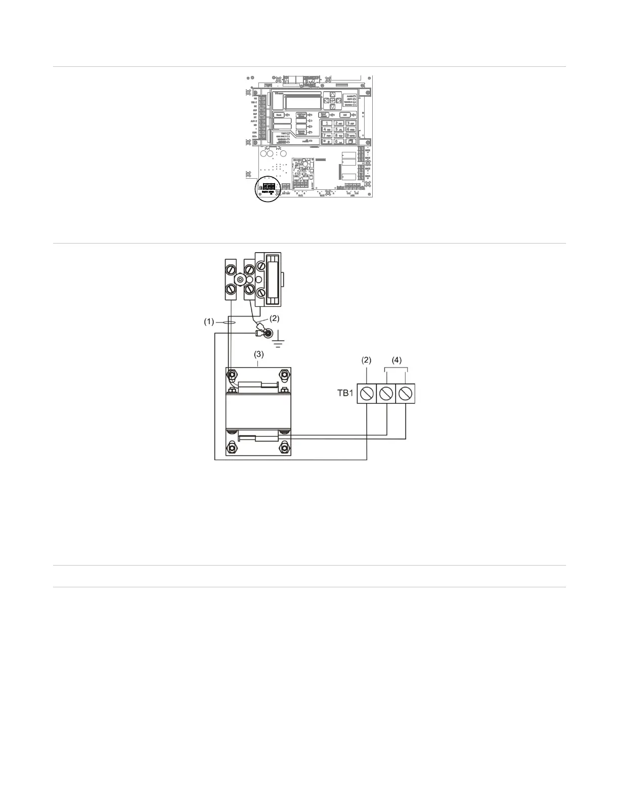
Figure 6: Transformer secondary wiring location
Figure 7: Transformer primary and secondary wiring
(1) 120 or 230 VAC IN
(2) Earth ground
(3) Transformer
(4) 24 VAC IN
Battery wiring (TB8)
Caution: Connect and disconnect standby batteries only with the AC power applied.
The control panel has a 24 VDC rechargeable battery circuit that is capable of charging up to
two 12 VDC, 26 Ah sealed lead acid batteries.
The table below lists the batteries that can be installed in the control panel cabinets. Up to two
11 Ah batteries will fit in the VS1 control panel cabinet and two 18 Ah batteries will fit in the
VS4 point control panel cabinet. If larger batteries are required, you must use an approved
battery cabinet. To determine which battery the system requires, use the “Battery calculation
worksheet” on page 190.