Chapter 1: Installation and wiring
P/N 3102351-EN • REV 005 • ISS 28DEC18 17
Figure 21: Terminal wiring location
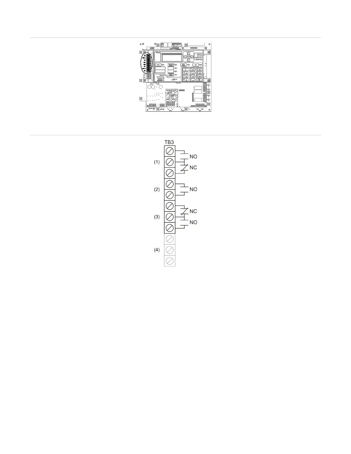
Figure 22: Relay wiring terminals
(1) Common trouble relay
(2) Common supervisory relay
(3) Common alarm relay
(4) Auxiliary/Smoke power output
Note: The figure above shows the panel in a normal state.
Remote annunciator wiring (TB4)
The control panel provides a connection for up to eight remote annunciators.
Circuit specifications
• Class B or Class A
Note: The VS1 panel requires the SA-CLA card to support Class A and redundant Class B
circuits. Refer to “SA-CLA wiring” on page 26, or to installation sheet P/N 3101094-EN.
• Circuit voltage: 2.55 V peak-to-peak average