H11O566A
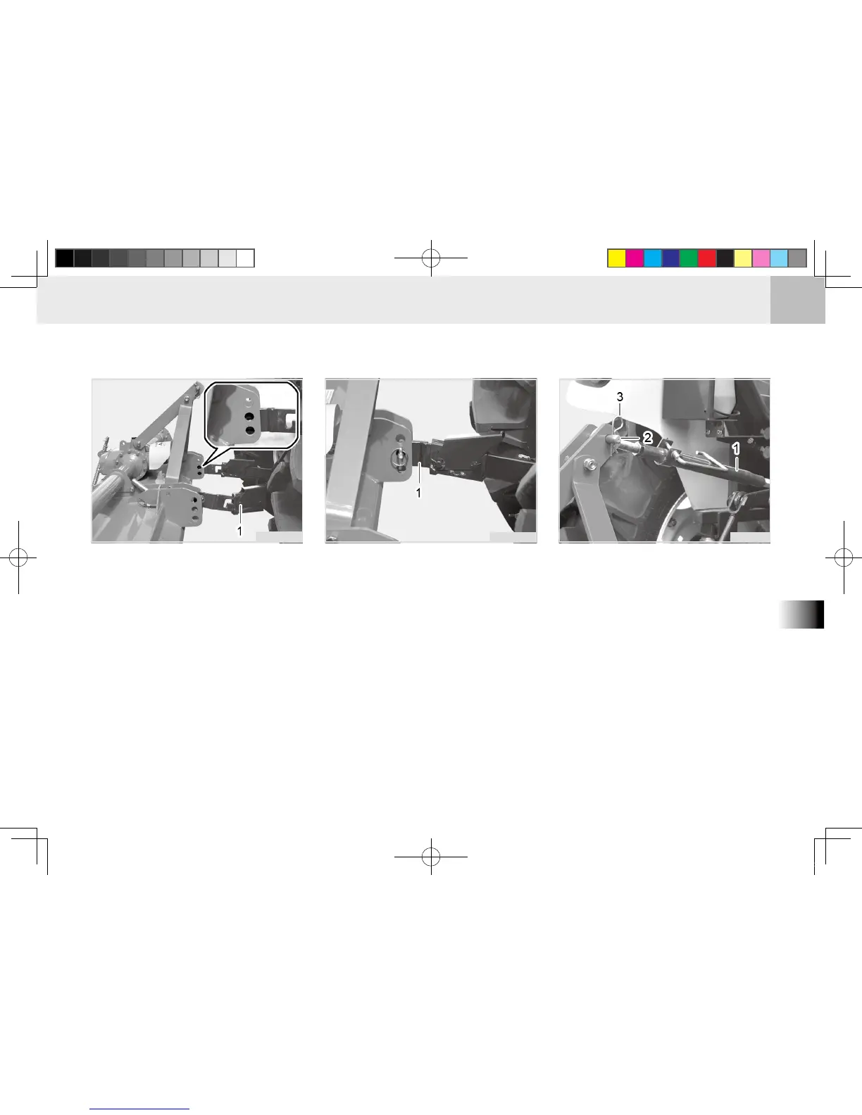
5. Install the lower link to the imple-
ment and t the pins.
(1) Lower Link
6. Start the engine and drive back-
ward toward the implement. Then,
the lower link end is inserted to its
original position.
(1) Lower Link End
H11O569A
7. Sep arate the top lin k fro m its
bracket and turn it to adjust its
length so that it becomes close to
the upper bracket mounting hole
of the implement. Then, t it to the
mounting hole, insert the lock pins,
and secure it with the snap pin.
Remove the implement support as
necessary.
(1) Top Link (3) Snap Pin
(2) Lock pin
H11O561A